
BLDC drive + cycloidal reducer
Brushless Motor Cycloidal Reducer Noise Troubleshooting
Check frequencies, narrow the inspection route, then review the evidence.
Published · Reviewed · Micro Cycloidal editorial team
1. Four decisions before replacing a reducer
Compare matched operating conditions
Hold speed, load, mounting and sensor position constant before comparing recordings. A change in the test setup can change the apparent symptom.
SKF: Spectrum Analysis, Jason MaisSeparate electrical and mechanical hypotheses
PWM and current distortion can produce motor noise. A qualified, guarded motor-only comparison can narrow the search, but removing the load also changes the excitation.
Texas Instruments: BLDC audible noise control, SSZTCX2 (2023)Use the model manual for acceptance
Noise, runout, temperature and lubrication limits need an identified reducer and test condition. Generic green zones cannot authorize continued service.
Sumitomo: Cyclo 6000 operation and maintenance, v7Treat grease condition as evidence
Churning and starvation are different mechanisms. Check the service history and approved lubricant before adding or removing grease.
SKF: Grease lubrication mechanisms in rolling bearing systems (2013)The inspection routes below are editorial screening suggestions. They are not a measured fault classifier, a statistical confidence score or a substitute for the installed machine procedure.
2. Measurements, acceptance limits & standards
Sound pressure at one microphone and source sound power are different quantities. ISO 3744:2025 covers determining sound power from sound-pressure measurements under specified environmental conditions. The 2010 edition is withdrawn. A phone recording can document a symptom, but cannot establish compliance. ISO 3744:2025 — Sound power measurement
Check sensor bandwidth, sample rate, anti-alias filtering and mounting before interpreting a reference order. A low output order such as 0.862 Hz may be outside the recording chain bandwidth; use a suitable time record or modulation analysis rather than expecting a direct microphone peak. Phone processing can also alter a tone.
ISO 20816-9:2020 covers gear units rated 10 kW–100 MW at 30–12,000 r/min in specified steady-state conditions. Its applicability must be checked for a compact servo assembly; run-up and load transients are outside that scope. We do not assign A–D zones from a single RMS input. ISO 20816-9:2020 — Gear unit vibration
| Record | Known from this page | Still required |
|---|---|---|
| Shaft speed | User input, converted to reference Hz | Measured speed at the same operating point |
| Vibration RMS | Optional user log only; no grade | Sensor location, direction, bandwidth and OEM baseline |
| Housing temperature | Optional user log only; no grade | Ambient, trend, load and model alarm limits |
| Sound level | Not measured or predicted | Instrument, weighting, geometry, background and test method |
| Acceptance | Unknown | Model-specific limits and a repeatable acceptance test |
3. What the frequency checker calculates
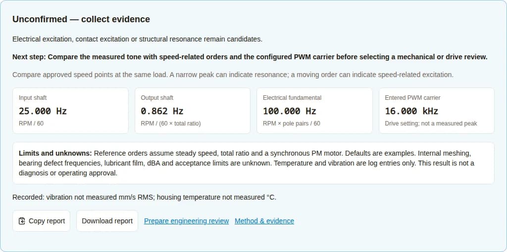
The following reference orders are arithmetic consequences of the entered speed, total ratio and pole pairs. They assume a synchronous permanent-magnet motor at steady speed. Use speed magnitude for reverse motion; the tool does not infer direction, internal stage speeds or acoustic amplitude.
| Reference | Calculation | Example / interpretation |
|---|---|---|
| Input shaft | f_in = n / 60 | 25.000 Hz; rotational reference, not proof of eccentric damage |
| Output shaft | f_out = n / (60 × R_total) | 0.862 Hz; total output rotation |
| Electrical fundamental | f_e = n × pole pairs / 60 | 100.000 Hz; motor electrical reference |
| PWM carrier | Entered drive setting | 16.000 kHz; configured carrier, not a measured spectrum |
| Bearing / internal mesh | Not calculated | Unknown without bearing and stage data |
At 0 RPM, shaft and electrical rotational orders are zero, while an energized inverter can still switch. A current-loop oscillation has its own dynamics and is not predicted by these formulas. Defaults demonstrate the method and must be confirmed.
For spectrum interpretation and the need for corroboration: SKF: Spectrum Analysis, Jason Mais.
4. Contact pattern & transmission error
Contact-pattern and transmission-error investigation belongs after external operating conditions have been checked. Request a model-specific design or metrology review for a persistent load-related tone. The installed profile, clearance strategy, material and loading are not available to this checker.
Public evidence reviewed here does not establish a universal profile offset, contact stress, engagement percentage, arcsecond target or dBA improvement for this assembly. Do not rework discs or substitute pins based on a generic online value.
5. Pilot, coupling & mounting alignment
Sumitomo lists alignment, installation flatness, base rigidity and vibration transmitted from the driven machine among checks for abnormal noise. Apply those categories to the installed assembly with its own drawings. Sumitomo: Cyclo 6000 operation and maintenance, v7
| Check | Record | Acceptance basis |
|---|---|---|
| Motor pilot | Datum, radial indication and clamping state | Approved interface drawing |
| Flange face | Face indication and mounting condition | Model assembly procedure |
| Coupling | Type, engagement and fastener record | Coupling / reducer instructions |
| Lost motion | Test torque, direction and angle | Specified model test; never assume rated torque |
6. BLDC drive, PWM & current distortion
TI describes PWM modulation and dead-time compensation as ways to address electrical audible noise. Modulation choices also change current ripple and switching losses. Its examples do not validate a gain reduction or filter setting for an arbitrary servo. Texas Instruments: BLDC audible noise control, SSZTCX2 (2023)
Save the current configuration and capture current, speed and feedback traces for a qualified drive review. A higher switching frequency may change the tone while increasing heat. An uncoupled comparison changes the load, so a quieter motor does not conclusively clear the drive.
7. Bearing fault frequencies need actual geometry
For a conventional stationary-outer-race bearing, SKF gives BPFO = (N_b/2) × f_r × (1 − (B_d/P_d) cos α); BPFI uses the plus sign. N_b is rolling-element count, B_d rolling-element diameter, P_d pitch diameter, α contact angle and f_r inner-race rotation rate relative to the stationary outer race. Do not substitute catalogue bore or outside diameter for B_d or P_d. Eccentric or moving-race arrangements need a model-specific relative-motion analysis. SKF: Spectrum Analysis, Jason Mais
The checker intentionally leaves these frequencies unknown. Obtain the exact bearing designation or supplier frequency factors and compare an appropriate spectrum. Disc phasing, preload and disassembly instructions also depend on the reducer design.
8. Internal stage architecture changes the interpretation
| Architecture | What total ratio provides | Missing for internal orders |
|---|---|---|
| Single cycloidal stage | Overall output speed magnitude | Fixed/moving members, lobe and pin counts, signed relative speeds |
| Compound RV architecture | Overall output speed magnitude | Input gear stage, eccentric speed and cycloidal stage geometry |
| Integrated joint with unknown internals | Output reference only if total ratio is known | Supplier kinematic diagram and bearing IDs |
Do not interpret total motor speed as every internal bearing or eccentric speed. Request the kinematic diagram before assigning an internal mesh peak. The tool makes no single-stage assumption.
9. Lubrication, churning & temperature
SKF distinguishes initial churning from later lubricant supply and starvation in rolling bearings. Excess grease can sustain churning losses and high temperatures. Film formation depends on lubricant supply and properties, not housing temperature alone. SKF: Grease lubrication mechanisms in rolling bearing systems (2013)
| Observation | Possible investigation | Required before action |
|---|---|---|
| Noise after relubrication | Churning, compatibility or a service error | Lubricant identity, added mass and model fill procedure |
| Noise on cold start | Starting drag or lubricant supply | Ambient and approved starting conditions |
| Heat with load | Loading, friction or cooling | Temperature history and model ratings |
| Visible debris | Contamination or wear | Preserve a sample under the service procedure; request inspection |
No fill percentage, lubricant grade, film ratio or sound-level prediction is prescribed here. A lambda ratio requires a contact-film model and measured roughness; it cannot be converted into a general dBA value.
10. Structure, resonance & acoustic amplification
A mounting structure can change what is heard. Compare approved speed points with a consistent microphone and sensor setup, and record the mounting configuration. Do not loosen fasteners on a running unit or insert compliant mounts without checking alignment, stiffness and load paths.
Distinguish a moving excitation order from a repeatable response peak. No universal dBA reduction is promised for thicker plates, damping or isolation; evaluate the full motion system after any authorized change.
11. Manual evidence checklist & isolation route
Use this route when parameters are missing, JavaScript is unavailable or the tool is inconclusive. Powered comparisons require the machine procedure. Internal inspection and overhaul should follow the authorized service process. Sumitomo: Cyclo 6000 operation and maintenance, v7
1. Secure and identify
Stop for grinding, impacts, leakage, rapid deterioration or a machine alarm. Isolate energy and secure gravity-loaded axes before uncoupling or inspection.
Deliverable: Record motor, drive and reducer model, serial number, service history and approved limits. For a braked axis, secure the load and verify brake-release status through the machine procedure before any comparison.
2. Capture a repeatable baseline
If operation is permitted by the machine procedure, record speed, load, temperature, microphone position and vibration sensor direction together.
Deliverable: Keep the original waveform and spectrum; record bandwidth, units and instrument settings.
3. Compare one variable
Within approved conditions, compare speed or load at a time. Motor-only operation requires a secured motor, guarded shaft and an approved controller setup.
Deliverable: A quieter uncoupled motor narrows the hypotheses; it does not prove the reducer is faulty.
4. Review and verify
Send the evidence to the drive or reducer supplier before teardown, tuning or lubrication changes. Recheck the same operating point after an approved correction.
Deliverable: Return to service follows the machine acceptance procedure, not this calculator.
12. Worked scenarios — illustrative, not field results
These hypothetical examples show how to use the checker. They are not customer records, measured repair outcomes or performance guarantees.
Whine while holding position
Assumptions: Assume a stationary axis with a 16 kHz drive setting.
Symptom: A tone is present at zero shaft speed.
Process: Input 0 RPM and holding condition. Rotational reference orders become zero while the entered PWM reference remains 16 kHz. Compare drive current and feedback under an approved test.
Decision: Electrical/control excitation remains a candidate. A tone near the carrier does not identify a failed part or prove a filter setting.
Knock that follows input speed
Assumptions: Assume 1,800 RPM, total ratio 29:1 and four pole pairs.
Symptom: A recurring knock gets faster with the motor.
Process: The reference orders are 30 Hz input, 1.034 Hz output and 120 Hz electrical. Compare measured orders and obtain the actual bearing designation.
Decision: Do not substitute an assumed needle count for bearing data. The next deliverable is a matched spectrum and supplier inspection decision.
Rumble under payload
Assumptions: Assume 1,500 RPM and a load-sensitive rumble.
Symptom: The symptom decreases when payload is removed.
Process: Select high torque and rumble. Record payload position, moment load and mounting condition against the model ratings.
Decision: Bearing loading, alignment and structural response remain competing explanations; the tool does not estimate allowable payload.
Noise after relubrication
Assumptions: Assume a service event followed by rising temperature.
Symptom: Noise and idle current changed after grease was added.
Process: Select thermal rise and attach lubricant identity, added mass and temperature history. Compare with the model service instructions.
Decision: Review the fill procedure and compatibility with the supplier. No universal fill percentage or predicted dBA improvement is available.
13. Test choices, cost & misuse risk
| Option | Value / limitation | Cost or risk | Mitigation / alternative |
|---|---|---|---|
| Repeat a matched recording | Shows symptom repeatability; not calibrated acceptance | Low effort; changed setup can mislead | Document settings and retain original files |
| Motor-only comparison | Narrows hypotheses; load has changed | Fixture time, exposed shaft and gravity-load risks | Use qualified staff and guards; review current traces if uncoupling is unsuitable |
| Drive tuning review | Can investigate electrical excitation | Thermal or stability regression, downtime | Save parameters and use vendor validation |
| Lubrication service | Can address a verified service discrepancy | Wrong grease, overfill, contamination or warranty impact | Confirm model instructions and service authority |
| Teardown / metrology | Can inspect internal contact and damage | Highest downtime and assembly risk | Supplier inspection after external evidence review |
If no model-specific limit or safe test procedure is available, keep the acceptance decision open and send existing evidence for review. A lower sound level alone does not verify serviceability.
14. Engineering decision FAQ
Interpret the result
Does this tool identify the failed component?
No. It provides frequency references and a symptom-led inspection route. It does not analyze audio, a measured spectrum or machine history.
SKF: Spectrum Analysis, Jason MaisWhat noise level is acceptable?
Use a model-specific acceptance test with defined operating conditions. ISO 3744 describes sound-power measurement; it does not set a general reducer noise limit.
ISO 3744:2025 — Sound power measurementCan ISO 20816-9 automatically grade a small robot joint?
The published scope starts at 10 kW and addresses specified steady-state gear-unit measurements. Applicability must be established before any acceptance grading.
ISO 20816-9:2020 — Gear unit vibrationWhy are bearing frequencies shown as unknown?
The bearing designation, internal geometry and relative race speeds were not entered. Inventing those values would make a numerical result misleading.
SKF: Spectrum Analysis, Jason MaisCan a peak at one reference frequency prove a defect?
No. Look for corroborating orders, trends and other measurements. Several sources can overlap at the same frequency.
SKF: Spectrum Analysis, Jason MaisMotor and operating condition
Can the motor make noise at zero speed?
Yes. An energized drive can still generate switching or control excitation while the shaft is stationary. Use the holding condition and enter zero speed.
Texas Instruments: BLDC audible noise control, SSZTCX2 (2023)Should I raise PWM frequency to fix a whistle?
Only within the drive and motor instructions. Modulation changes affect current ripple and switching losses; an audible improvement alone does not validate thermal operation.
Texas Instruments: BLDC audible noise control, SSZTCX2 (2023)Does quiet motor-only operation clear the motor?
It narrows the search, but unloading changes the excitation and boundary conditions. Compare coupled current, speed and load as well.
Texas Instruments: BLDC audible noise control, SSZTCX2 (2023)Why does the checker leave internal contact orders unknown?
Total ratio establishes the overall output reference only. Internal contact orders need the model construction drawing, stage speeds and tooth or pin counts. The linked manual illustrates model-specific one- and two-stage construction; it does not provide a universal RV contact formula.
Sumitomo: Cyclo 6000 operation and maintenance, v7What if I do not know pole pairs or PWM?
The defaults are illustrative. Replace them from the motor and drive configuration, or treat electrical results as unconfirmed references.
Texas Instruments: BLDC audible noise control, SSZTCX2 (2023)Inspection and next steps
What pilot runout or backlash should I accept?
Use the approved model drawing, datum and measurement procedure. A tolerance quoted for another reducer is not a substitute.
Sumitomo: Cyclo 6000 operation and maintenance, v7Does cold-start noise mean it is safe to warm up?
No. Compare the allowed lubricant and starting conditions first; stop for deterioration or machine alarms. The tool cannot authorize a warm-up cycle.
SKF: Grease lubrication mechanisms in rolling bearing systems (2013)Can housing temperature predict lubricant film thickness?
Not alone. Lubricant properties, contact geometry, loading, roughness and lubricant supply are also needed. No film thickness or dBA forecast is calculated here.
SKF: Grease lubrication mechanisms in rolling bearing systems (2013)Should I add grease when noise increases?
Check the model service procedure first. Adding grease without knowing the current quantity or compatibility can worsen the condition.
Sumitomo: Cyclo 6000 operation and maintenance, v7Can I open the reducer to check the discs?
Arrange authorized service and follow the assembly procedure. Disc phasing and internal preload are design-specific.
Sumitomo: Cyclo 6000 operation and maintenance, v7What should I send for engineering review?
Send model IDs, speed/load, a symptom timeline, measured waveform and spectrum, sensor settings, mounting drawings and service history. Label missing data as unknown.
SKF: Spectrum Analysis, Jason Mais15. Sources, uncertainty & engineering review
Source check: . References support the named mechanisms and scope boundaries. Public abstracts do not establish compliance; the installed unit manual and full applicable standard govern an acceptance test. No measured customer dataset was used.
About the Micro Cycloidal editorial publisher- Sumitomo: Cyclo 6000 operation and maintenance, v7
Safety precautions; §7 Operation; §8 Lubrication; §9 Troubleshooting.
Scope / limitation: Industrial Cyclo product guidance; dimensions, lubricant quantities and ratings must come from the installed model manual.
- ISO 20816-9:2020 — Gear unit vibration
Public abstract: power, speed, steady-state and acceptance-test scope; confirmed in 2026.
Scope / limitation: 10 kW–100 MW and 30–12,000 r/min; no universal compact servo acceptance threshold is established here. Full normative tables have not been reproduced.
- ISO 3744:2025 — Sound power measurement
Public abstract and edition status; replaces ISO 3744:2010.
Scope / limitation: A sound-power measurement method, not a universal dBA pass/fail limit or a single microphone reading.
- SKF: Spectrum Analysis, Jason Mais
§3–4 Measurement context and corroboration; §9 Rolling element bearing defects, printed p. 18 for equations.
Scope / limitation: Bearing frequency equations require actual geometry, contact angle and relative race speed. A spectral peak alone does not establish the cause.
- Texas Instruments: BLDC audible noise control, SSZTCX2 (2023)
PWM and Dead-time compensation sections.
Scope / limitation: Explains electrical noise mechanisms and switching-loss tradeoffs; does not prescribe universal servo gains or filter frequencies.
- SKF: Grease lubrication mechanisms in rolling bearing systems (2013)
Phases in grease lubrication; Film thickness; Grease life and relubrication.
Scope / limitation: Bearing lubrication mechanisms; no general gearbox fill percentage or conversion from film ratio to dBA.
Request a review of your evidence
Share the checker report, motor/drive/reducer IDs, speed and load, symptom timeline, recordings, sensor settings, mounting drawings and service history. Mark missing details as unknown. A confirmed root cause may require more measurements or physical inspection; no turnaround or repair outcome is guaranteed.
Inquiry Email
Attach the downloaded report, original recordings, spectra and mounting drawings in your email client.
Instant Chat
WhatsApp Engineering Support
Start with model IDs, operating speed/load and the symptom timeline.