
1. Four decisions before releasing the flange
Separate interface size from load capacity
An ISO flange designation helps match tooling. Bearing, joint and flange strength require separate evidence.
ISO 9409-1:2004 — robot mechanical interface platesKeep missing bearing data visible
Use the actual bearing model and installed stiffness before making a load, tilt or life decision.
THK — Cross-Roller Ring nominal life and load selectionMeasure the fit through a thermal cycle
Model-specific fit guidance takes precedence over a generic preload or sleeve prescription.
THK — Cross-Roller Ring fit guidanceUse residual clamp in a slip estimate
A bolt proof or assembly load is not automatically the remaining clamp under service loads.
VDI 2230 Part 1:2015-11 — highly stressed bolted joints2. Calculation method, assumptions and unknowns
The equations below are transparent screening relations. Zero loads are supported; empty required values and values outside the displayed tool ranges stop calculation. Optional fields remain unknown until supplied. Calculation is synchronous and runs locally.
| Output | Equation | Units and limits |
|---|---|---|
| Bending moment | M = (Fr × L + Fa × r) / 1000 | N and mm → Nm; conservative sum of magnitudes; a vector load model may give a different resultant |
| Inner / outer ligament | (PCD − hole − bore) / 2; (OD − PCD − hole) / 2 | mm; hole envelope only, no thread, stress or fatigue criterion |
| Adjacent hole gap | PCD × sin(π / bolt count) − hole | mm; equally spaced centers; nonpositive gap is a conflict |
| Angular tilt | θ = M / installed stiffness | Nm / (Nm/mrad) → mrad; multiply by 206.264806 for arcsec |
| Friction torque | T = μ × bolt count × residual clamp × effective radius | kN × mm → Nm; one interface, uniform remaining clamp; no pin capacity added |
| Free thermal mismatch | ΔD = D × (α seat × ΔT seat − α ring × ΔT ring) / 1000 | D in mm, α in µm/m·K → µm; positive means seat grows more than ring |
3. Interface geometry: match drawings before assigning loads
A tooling interface and a reducer support bearing solve different problems. Match the mechanical interface on the mating drawing, then verify the support and joint against the load cases.
| Feature | Review | Evidence needed | Boundary |
|---|---|---|---|
| Tooling interface | PCD, thread size/depth, pilot, pin position and clocking | ISO designation plus controlled mating drawing | ISO 9409-1 does not supply a bearing or joint rating |
| Bore and holes | Inner, outer and neighboring hole envelopes | Largest envelope at every flange section | Positive clearance alone does not establish fatigue strength |
| Fastener access | Head, washer, counterbore and wrench sweep | Assembly tool model and section drawing | Tool calculation only covers the circular envelope entered |
| Locating features | Pilot fit and locating-pin strategy | Tolerance stack at cold and hot states | Do not assume two cylindrical pins share shear equally |
4. Compare complete bearing support architectures
The following is a design comparison, not a ranking of interchangeable bearing sizes. Include the housing, retaining rings, mounting bolts and support span in a stiffness comparison.
| Architecture | Reason to consider | Main uncertainty | Next step |
|---|---|---|---|
| Cross-roller ring | Compact support for combined loads | Model-specific preload, fit, mounting-ring flexibility and installed stiffness | Obtain load interaction and moment/deflection data |
| Back-to-back angular-contact pair | Useful when axial span is available | Preload, pair spacing, contact angle and housing stiffness | Compare the complete supported assembly |
| Four-point contact bearing | Potential compact alternative | Contact transitions, moment capability and friction | Require supplier approval for the load spectrum |
| Radial bearing plus separate thrust support | Separates support functions | Assembly length, load sharing and alignment | Evaluate all support reactions together |
No universal CC0 contact arc, stiffness multiplier or MPa stress is asserted. Use the selected manufacturer’s clearance designation and load-dependent curve.
THK — Cross-Roller Ring fit guidance5. Distinguish output torque, bending moment and tilt
Output torque acts about the shaft axis. Radial force at an axial overhang and axial force at a radial offset create bending about the bearing support. Supply all concurrent components to the reducer and bearing suppliers.
The screen adds the two bending magnitudes conservatively. For an actual load spectrum, resolve vectors and include acceleration, braking, impacts and changing arm orientation.
With supplied installed stiffness Cθ, θ = M / Cθ. A small-angle tool-tip contribution is approximately reach × θ in radians; add other compliance and positioning errors separately.
6. BLDC heat: model both sides of each fit
Free thermal growth is a first comparison. Actual fit pressure depends on geometry, restraint, temperature gradients and tolerances. A seat that grows more than its steel outer ring may loosen the fit; it does not automatically squeeze the rollers.
| Condition | Possible effect | Verification |
|---|---|---|
| Seat grows more than outer ring | Outer-ring fit may loosen | Measure both temperatures and hot fit; assess ring retention |
| Ring grows more than seat | Fit interference may increase | Review ring distortion and clearance with the bearing supplier |
| Inner ring is hotter than outer ring | Internal clearance may change | Model the complete bearing, not just seat diameter |
| Steel sleeve in aluminum housing | Adds a second fit and assembly operation | Check both interfaces, wall compliance and hot/cold retention; no universal H7/s6 prescription |
7. Bolting and dowels: keep load paths explicit
The friction estimate uses user-supplied minimum residual clamp and effective contact radius. It does not derive tightening torque from bolt size, add dowel strength or distribute external bending to individual fasteners. A ratio above one is an arithmetic comparison, not a safety factor.
For release, establish assembly scatter, embedment loss, thermal load changes, joint separation, transverse slip, bolt stress and thread stripping. A locating pin needs its own shear, bearing-pressure, fit and edge-distance checks; do not assume pins and friction reach their limits together.
VDI 2230 Part 1:2015-11 — highly stressed bolted joints8. Allocate runout and stiffness to a tool-point budget
Start with allowed tool-point error and reach. Allocate contributions to bearing tilt, housing deformation, flange runout, coupling alignment and control error. Define datums, measurement radius, mounting condition and temperature on the inspection plan.
A geometric tolerancing standard supplies a specification language; it does not set a universal 5 µm flange limit. Record radial and face runout traces through the intended rotation range, and measure loaded tilt separately. Flatness is a form tolerance and is specified without a datum reference.
9. Choose material and heat treatment as a manufacturing system
A steel flange can simplify bearing-seat compatibility; a lightweight alloy may reduce inertia while changing stiffness, wear, thread behavior and thermal fits. A sleeve or insert adds machining, retention and tolerance-stack costs. Compare complete part mass and process cost at the required life.
Specify grade, product condition, heat treatment, hardness depth where relevant, finish allowance and inspection sequence on the drawing. Use certified material properties. This guide does not equate regional grades or assign generic fatigue limits, anodize HRC values or medical/MRI suitability.
10. Make seals and hollow-bore routing part of the layout
Choose seals against speed, temperature, lubricant chemistry, ingress and friction targets using the exact seal datasheet. A V-ring is a contact element; a labyrinth plus V-ring assembly cannot be assumed to have zero drag or unlimited speed.
For cables, check the selected part’s dynamic bend radius, torsion rating, allowable moving length, connector envelope and shielding termination. A protocol such as EtherCAT does not define those mechanical limits. A service loop suits finite rotation; continuous rotation may require rotary electrical or pneumatic transfer.
Deburr and protect bore mouths, restrain the harness, then verify the complete motion envelope and life cycle. Do not infer a universal bore size from cable diameter alone.
11. Bearing life requires a selected bearing and duty cycle
The screen deliberately leaves bearing life unknown. Obtain the actual dynamic and static ratings, the manufacturer’s equivalent-load method, speed/oscillation conditions, preload and lubrication requirements. A C/P ratio is not a static safety factor.
Check peak-load indentation separately from rolling fatigue. A small-angle reversing actuator also needs an evaluation of fretting and lubricant replenishment. Changing the bearing pitch diameter alone cannot establish life or moment rigidity.
THK — Cross-Roller Ring nominal life and load selection12. Risks, cost and scenario mismatch
| Risk | Consequence | Action |
|---|---|---|
| Misuse: treating screening as approval | Unsupported bearing or flange strength decision | Obtain combined-load ratings, stress/fatigue analysis and prototype evidence |
| Cost: demanding tight runout without a budget | Extra grinding, inspection and scrap | Allocate tool-point error to each component before selecting drawing tolerances |
| Scene mismatch: small-angle reversing joint | Lubrication/fretting behavior differs from continuous rotation | Ask the bearing supplier for oscillatory-duty evaluation |
| Joint slip or separation | Lost clamp, fretting and fastener fatigue | Verify minimum service clamp, contact pressure and load distribution |
| Cable routing through rotating bore | Twist accumulation, abrasion or connector interference | Use the cable part datasheet, service loop, full-motion test or rotary transfer |
These are review priorities, not a field-failure frequency dataset. Stop prototype operation when binding, unexpected current rise, slipping or excessive play occurs and inspect the assembly before increasing preload.
13. Release sequence and evidence checklist
- Freeze interface revision and establish concurrent load cases and environment.
- Run this screen; resolve conflicts and list missing supplier data.
- Complete bearing, flange and joint analysis with reviewed assumptions.
- Build a prototype and record the measurements below against project limits.
| Check | Record | Acceptance source |
|---|---|---|
| Runout and flatness | Datum scheme, radial/face measurement trace and temperature | Project drawing limits from tool-point error budget |
| Bearing behavior | Installed moment/tilt curve, starting torque and load spectrum | Selected bearing and assembly supplier limits |
| Thermal assembly | Seat/ring temperatures, drag, current and fit through hot/cold cycles | Project limits after supplier review |
| Bolted joint | Tightening process, residual clamp, separation/slip and fatigue calculation | Approved joint analysis and assembly procedure |
| Seals and cables | Leak/ingress test and full motion-cycle routing test | Specified environment, cable datasheet and service target |
14. Worked examples with explicit assumptions
These are constructed calculations, not customer projects, measurements or validated product specifications.
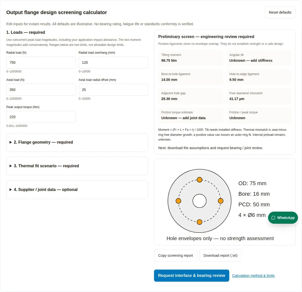
Illustrative wrist: resolve the moment first
Inputs: Fr = 750 N at L = 120 mm; Fa = 350 N at r = 25 mm.
Calculation: (750 × 120 + 350 × 25) / 1000 = 98.75 Nm.
Decision: Send 98.75 Nm and concurrent peak torque to the bearing supplier. If installed stiffness is supplied as 500 Nm/mrad, the linear estimate is 0.1975 mrad (40.74 arcsec). Neither value validates life.
Illustrative compact flange: detect a hole conflict
Inputs: OD = 75 mm; bore = 46 mm; PCD = 50 mm; hole envelope = 6 mm.
Calculation: (50 − 6 − 46) / 2 = −1 mm inner ligament.
Decision: The hole overlaps the bore. Revise bore, bolt circle or flange size before stress analysis. A larger OD alone does not fix this inner overlap.
Illustrative thermal comparison: distinguish radius and diameter
Inputs: D = 75 mm; α seat = 23.4, α ring = 11.2 µm/m·K; both rise 45°C.
Calculation: 75 × (23.4 × 45 − 11.2 × 45) / 1000 = 41.175 µm diametral mismatch.
Decision: The corresponding free radial difference is 20.5875 µm. This is not the bearing internal clearance change; restraint and thermal gradients need a separate model.
15. Engineering decision FAQ
Using the screen
What result can I use immediately?
Use the load moment and hole-envelope clearances to prepare a design review. Optional stiffness and joint data add conditional estimates. The screen does not approve a design.
Why is angular tilt unknown by default?
Diameter does not establish installed stiffness. Supply a measured or vendor-supported assembly moment stiffness at the load of interest.
Does a positive ligament mean the flange is strong enough?
It only means the entered circular envelopes do not overlap. Flange thickness, stress concentration, thread engagement, material state and fatigue remain to be checked.
How are opposite load directions treated?
The tool adds moment magnitudes as a conservative scalar envelope. Use a vector load model for known directions and evaluate concurrent load cases, not unrelated independent peaks.
Interfaces and joints
Does ISO 9409-1 specify flange torque capacity?
No. Its public scope covers interface geometry, designation and marking and explicitly excludes correlation with load-carrying ranges. Use the actual robot, bearing and joint ratings.
Can I add friction torque and dowel shear capacities?
This tool does not add them. Load sharing depends on fit, contact compliance, slip sequence, pin bearing stress and joint geometry; verify a positive-drive design separately.
Where do residual clamp and effective radius come from?
Use minimum remaining clamp after service-load unloading, scatter, settlement and temperature effects. Derive effective friction radius from contact pressure and geometry. Neither comes automatically from bolt grade or bolt PCD.
Does a friction ratio over one prove joint safety?
No. It compares a conditional friction estimate with peak torque only. Combined shear, separation, contact pressure, fatigue and the required slip margin need joint analysis.
Thermal behavior and release
Can stator temperature substitute for ring temperature?
No. Use separate measured or modeled seat and ring temperatures at a common reference state. Heat paths and cooling can produce different rises.
Does an aluminum housing always squeeze the bearing?
No. Uniformly greater seat expansion can loosen an outer-ring fit. Internal preload depends on the complete temperature field, ring constraints and fits.
Is a steel sleeve always the right fix?
A sleeve changes two interfaces and their compliance. Compare its manufacturing and retention requirements with a different housing material, cooling or an independent support architecture.
What should I send for a detailed review?
Send a controlled interface drawing, concurrent load spectrum and duty cycle, bearing model/ratings/stiffness, material and temperature data, joint calculation, seal environment and cable part numbers.
16. Sources, evidence boundaries and review date
Published by Micro Cycloidal. Public source pages checked on . Standards abstracts establish scope; detailed dimension tables and full calculation procedures require the controlled standard or supplier document. The method table and worked examples are this page’s own screening calculations.
Public abstract: interface dimensions, designation and orientation; no load-capacity correlation.
Boundary: Confirm exact dimensions, thread depth, pilot and orientation against the controlled mating drawing and licensed standard. No torque or moment ratings are inferred here.
Manufacturer guidance: life uses the selected ring rating and equivalent load; preload, oscillation and lubrication affect applicability.
Boundary: No diameter-only load rating or universal life result is available. Ask THK about preload and small-angle oscillation.
Fit recommendations differ by ring model, clearance class and rotating ring. THK warns about excessive preload from interference in CC0 assemblies.
Boundary: No universal steel-sleeve interference, preload percentage or contact stress is specified by this page.
Publisher scope and FAQ: assembly scatter and preload losses must be considered when establishing minimum working clamp.
Boundary: This screen is not a complete VDI 2230 calculation. Bolt grade alone does not establish residual clamp or tightening torque.