
Micro Cycloidal Reducers for Surgical and Medical Robotics: Backlash, Torsional Rigidity, Cleanroom Sealing, and IEC 80601-2-77 Compliance
Select micro cycloidal reducers for surgical robotics: compare backlash, stiffness, thermal and sealing evidence, then prepare an application-specific OEM RFQ.
Published and reviewed: 6 November 2026. Scope: Global OEM engineering and procurement guidance for screening micro cycloidal reducers in surgical and medical robotics. Readers include mechanical designers, controls engineers, quality teams, and buyers selecting wrist, instrument-drive, imaging, and patient-side positioning axes. Dimensions and ratings must come from the proposed model's drawing and test records.
Evidence and modeling boundary: This is a selection framework with reproducible arithmetic examples, not a report of tested surgical hardware or a medical-device certification. Numerical examples are hypothetical inputs, not Microcycloidal product ratings or clinical acceptance limits. IEC 80601-2-77 compliance belongs to the complete applicable equipment or system; component selection alone cannot establish it. The device manufacturer must determine applicable editions, national requirements, essential performance, contact conditions, and validation responsibilities.
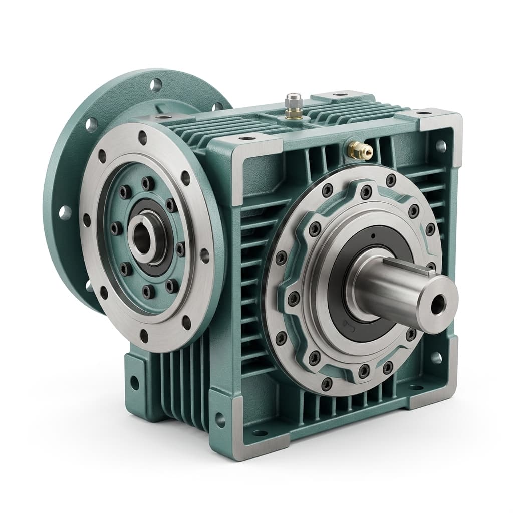
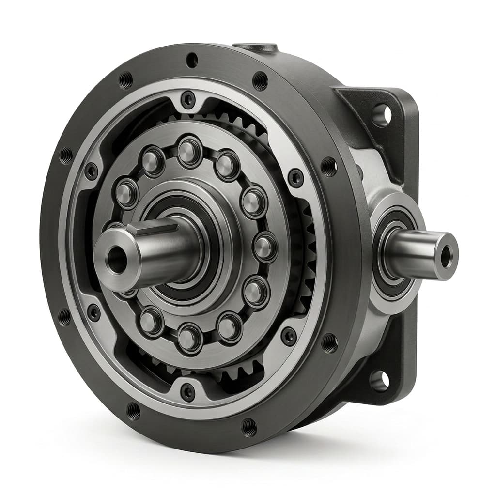
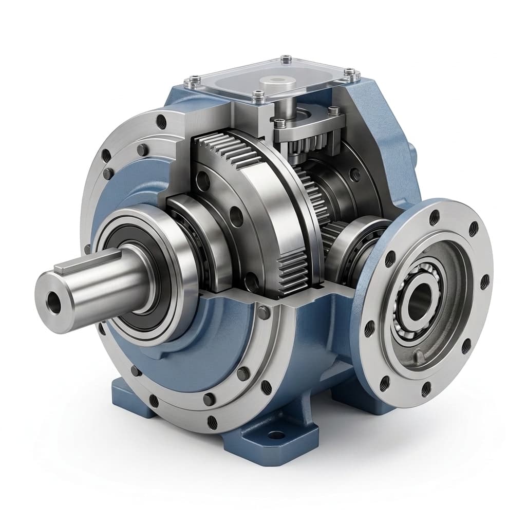
Illustration note: The header and product image below show a generic enclosed gearbox. They do not establish micro-scale dimensions, stainless-steel construction, sterilizability, or medical qualification.
Key Takeaways for Medical Robotics Engineering & Sourcing Leads
Micro cycloidal reducers are candidates when a compact joint needs reduction, controlled lost motion, and sufficient structural stiffness. Suitability depends on the assembled actuator, including bearings, motor, lubrication, seals, encoder mounts, and controls.
- Start with a joint error budget. Convert angular lost motion into tool-tip displacement using the actual geometry. Contributions combine through the manipulator Jacobian; they do not multiply automatically across joints.
- Compare matching test conditions. Backlash, lost motion, repeatability, torsional stiffness, and transmission error describe different behavior. A catalog number without its test method is insufficient for approval.
- Include friction in haptic assessment. Stiffness can reduce elastic deflection, but preload and reduction ratio can increase friction and reflected inertia. Stiffness alone does not establish force-feedback transparency.
- Separate overload and life evidence. A momentary peak rating does not demonstrate survival under repeated bone-cutting chatter. Request the waveform, duration, repetition count, and post-test acceptance criteria.
- Define thermal and sterile boundaries before ordering. Neither low drag torque nor a particular seal material proves an acceptable patient-contact temperature or validated reprocessing capability.
Evaluating a surgical wrist or patient-side axis? Use the checklist in Section 8 and request a gearhead application review with your envelope drawing, load history, and cleaning boundary.
1. Kinematic Precision: Backlash in Serial Surgical Linkages
The relevant mechanical question is how much positional uncertainty the transmission contributes at the instrument tip. The device team must allocate permitted error for the intended procedure. No universal gearbox accuracy figure qualifies all laparoscopic, orthopedic, or ophthalmic systems.
A Reproducible Tool-Tip Error Calculation
For small angular errors, a conservative positional bound is:
E_tip <= sum(r_i * abs(delta_theta_i))
delta_theta_i [rad] = lost_motion_i [arcmin] * pi / 10800
Here r_i is the perpendicular distance from joint axis i to the tip at the evaluated pose, in millimeters. The bound is in millimeters. A sum of downstream link lengths can substitute as a conservative geometric upper bound; it is not the exact lever arm at every pose. A full model uses delta_x = J(q) * delta_q, including joint-axis orientations.
Illustrative six-joint example: Assume lever-arm bounds of 550, 350, 150, 50, 30, and 10 mm, totaling 1,140 mm. At 1 arcmin angular uncertainty per joint, the bound is 1140 * pi / 10800 = 0.332 mm. At 8 arcmin per joint, the same geometry gives 2.653 mm. These compare assumed errors, not measured cycloidal and planetary performance.
If the design allocates 0.20 mm to this source, the equal per-joint allowance is approximately 0.20 / 1140 * 10800 / pi = 0.603 arcmin. Calibration error, structural compliance, bearing runout, thermal drift, and sensing uncertainty still require separate assessment. Check whether a supplier reports a full reversal width or a plus/minus error before using that number in the budget.
Request the output torque-angle hysteresis loop with test torque, speed, temperature, mounting, run-in state, and instrument resolution. Repeatability with one approach direction cannot replace a reversal test. Repeat the agreed acceptance method after endurance and required reprocessing exposures.
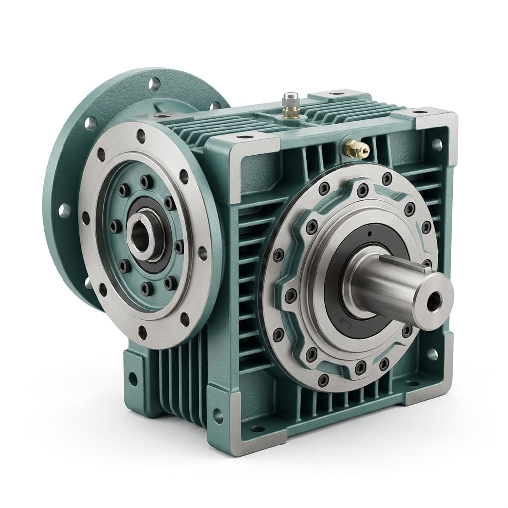
Generic packaging illustration only; this is not a dimensioned surgical gearhead drawing or evidence of medical qualification.
2. Transmission Architecture Matrix: Surgical Robotics Trade-offs
Compare architectures at the same output torque, speed, lifetime, and assembled package boundary. This eight-row matrix identifies sample-evaluation questions rather than assigning unsupported universal ratings.
| Engineering metric | Micro cycloidal reducer | Strain wave drive | Miniature planetary | Direct drive torque motor |
|---|---|---|---|---|
| Package envelope | Check eccentric, output bearing, and pin-ring space | Check flexspline and wave-generator space | Check stage count and output support | Check motor diameter, cooling, and holding torque |
| Lost motion | Measure preload and reversal hysteresis | Distinguish backlash from elastic hysteresis | Measure clearance and reversal behavior | No gear backlash; mounts and sensing still contribute error |
| Torsional stiffness | Request loaded torque-angle curves | Request curves over the intended torque range | Include mesh and multi-stage compliance | Include structure and finite control-loop stiffness |
| Peak and repeated shock | Require model-specific duration and cycle limits | Require fatigue and peak limits | Require tooth and bearing limits | Check current, bearing, and structural limits |
| Haptic behavior | Measure friction, ripple, and backdriving torque | Measure friction and hysteresis | Assess stage friction and reversal deadband | Assess cogging, inertia, and control stability |
| Heat generation | Measure drag, loaded efficiency, and seal losses | Measure operating-point losses | Measure stage and seal losses | Measure winding and drive losses |
| Cleaning compatibility | Qualify the complete sealed assembly | Qualify the complete sealed assembly | Qualify the complete sealed assembly | Qualify windings, sensing, bearings, and seals |
| Lifecycle acceptance | Retest precision, leakage, and drag after duty | Retest precision and fatigue-related changes | Retest precision and wear-related changes | Retest bearings, sensing, insulation, and thermals |
Engineering Implications of the Comparison
A cycloidal design distributes load through multiple contacts, but sharing depends on geometry, manufacturing error, and elastic deformation. That does not justify a blanket 500% shock guarantee. A strain wave design's flexing element requires fatigue assessment; its presence does not prove failure in orthopedic service. Planetary arrangements can also use precision or preloaded designs. Obtain comparable data before excluding a family.
For a bone-cutting axis, use a measured or conservatively specified reaction-torque history, including stops and jams. For a teleoperated wrist, prioritize low-speed reversal, breakaway friction, and force-sensing location alongside stiffness. Select the architecture meeting the complete acceptance plan, including service access and validation cost.
3. Torsional Stiffness and Haptic Force-Feedback Transparency
For an approximately linear segment of a torque-angle curve, elastic angular deflection is phi = T / k_t. Keep units consistent: torque in Nm and stiffness in Nm/rad give radians; Nm/arcmin gives arcminutes. Do not add a complete measured hysteresis width if it already includes loaded elastic deflection.
For an illustrative stiffness of 2 Nm/arcmin, a 1 Nm load produces 0.5 arcmin elastic deflection. At a 100 mm lever arm this is about 0.0145 mm. This is arithmetic for assumed inputs, not a product stiffness claim or a prediction of surgical accuracy.
Ask for loading and unloading curves at small interaction torques as well as rated torque. Include compliance of the output bearing, housing, fasteners, and instrument coupling. A reducer in a rigid test fixture may behave differently in a slender wrist housing.
Haptic quality also depends on sensor bandwidth, filtering, delay, motor inertia, friction, and controller stability. Motor rotor inertia reflected to the output scales approximately with the square of reduction ratio. Increased reduction or preload may improve one positioning metric while making backdriving harder. Evaluate force reflection on the assembled mechanism over the intended speed and contact-force range.
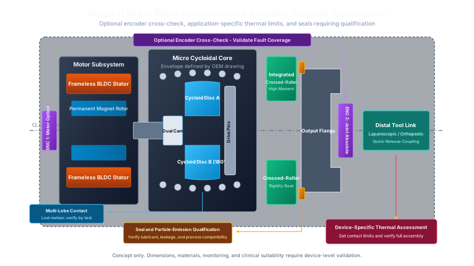
Concept schematic, not a validated safety architecture. Encoder arrangement, seal choice, thermal limits, and mechanical acceptance targets require application-specific qualification.
Before freezing an encoder or bearing stack, review prototype validation and hysteresis testing requirements with the intended fixture and operating conditions.
4. Thermal Management and Patient Safety: IEC 60601-1 Assessment
Set the Temperature Boundary Before Selecting Grease
IEC 60601-1 thermal assessment requires the applicable equipment classification, surface material, contact location and duration, ambient conditions, and relevant particular-standard requirements. A universal 41°C casing limit is not an adequate interpretation. The device team's regulatory and test specialists must establish limits and test conditions from controlled standard editions. If 41°C is chosen as an internal design target, label it as a project target.
Use an Energy Balance Without Double-Counting Losses
At a steady operating point, gearbox loss is P_loss = T_in * omega_in - T_out * omega_out. With total measured efficiency eta = P_out / P_in, the equivalent expression is P_loss = P_out * (1 / eta - 1). The expression P_out * (1 - eta) understates loss under this definition.
No-load screening uses P_drag = omega_in * T_0, with input-referred no-load torque measured at the stated speed and temperature. Do not add drag again when using total measured efficiency that already includes it. A separated model's load-dependent loss term must explicitly exclude no-load losses.
Illustrative thermal screen: At 3,000 rpm, input angular velocity is 314.16 rad/s. Input drag of 0.02 Nm would dissipate about 6.28 W without useful output work. Assuming assembly-to-ambient thermal resistance of 8 K/W, a simple steady-state model gives approximately 50 K temperature rise. This demonstrates why small torque alone cannot guarantee acceptable temperature. It is not a prediction for a particular actuator; actual heat paths, motion duty, motor losses, and drapes change the result.
Engineering Countermeasures to Validate
Use the reducer and lubricant suppliers' specified grease quantity, then verify coverage and temperature over life. There is no universal 15–25% fill ratio for every micro cycloidal geometry. Compare starting torque, running torque, leakage, wear, and temperature at cold start and thermal equilibrium.
Select lubricant chemistry using load, speed, compatibility, exposure route, and cleaning requirements. PFPE may suit certain environments, but chemistry alone establishes neither biocompatibility nor reprocessing suitability. NSF H1 incidental food-contact classification and USP Class VI material testing do not replace device-specific biological evaluation.
Provide a measured heat path into the supporting structure and evaluate the draped assembly at worst-case ambient and duty. Record accessible and patient-contact surfaces, sensor locations, duration, mounting, and acceptance limits. Include motor and brake heat even when the reducer supplier's report excludes them.
5. Cleanroom Particle Sealing and Sterilization Regimes
Choose the sterile boundary before specifying seal materials. A reducer behind an intact drape has a different qualification problem from a reusable tool exposed to sterilization. This six-row matrix specifies evidence to request; it is not a validated reprocessing instruction.
| Reprocessing or barrier method | Boundary to define | Potential concerns | Evidence before approval |
|---|---|---|---|
| Steam autoclave | Validated cycle, drying, and reuse count; 134°C is one possible requirement | Moisture ingress, corrosion, lubricant changes, encoder and adhesive damage | Complete-assembly cycle testing and post-cycle motion and sealing results |
| Vaporized hydrogen peroxide | Exact sterilizer process and permitted configuration | Vacuum exposure, oxidant compatibility, trapped volumes, residues | Process-specific validation; do not equate all VHP processes with plasma |
| Ethylene oxide | Validated cycle, packaging, and aeration | Residuals, absorption, and access to enclosed spaces | Residual assessment and processing validation for the actual assembly |
| Gamma or electron beam | Dose range, distribution, and repeat exposures | Polymer, lubricant, electronic, and adhesive degradation | Dose-specific material and assembled-device testing |
| Surface chemical disinfection | Named chemistry, concentration, wet time, and application | Seal swelling, coating damage, and liquid ingress | Repeated exposure and motion tests; an IP rating alone does not prove chemical compatibility |
| Sterile barrier drape | Interface, installation, movement, and replacement | Tears, coupling contamination, heat retention, and particles | Barrier-integrity and handling validation with the moving mechanism |
What ISO 14644-1 Establishes
ISO 14644-1:2015 classifies air cleanliness by airborne particle concentration. It does not certify a rotary seal, establish sterility, or measure biological contamination. Calling a seal “ISO Class 5 rated” without a defined component test and operating environment is insufficient.
Request a dynamic particle-emission test with background levels, particle sizes, sampling locations, speed, load, duration, and equipment calibration. Identify whether the requirement concerns manufacture, an enclosed clean zone, or use near a sterile field. No single cleanliness class applies automatically to all surgical axes. Keep lubricant migration, airborne emission, liquid ingress, and microbial barrier performance as separate criteria.
6. Functional Safety Architecture: IEC 80601-2-77 and Dual Encoders
The official IEC 80601-2-77:2019+AMD1:2023 consolidated publication covers basic safety and essential performance of robotically assisted surgical equipment and systems, including interaction and interface conditions. Its public abstract does not prescribe this actuator's encoder design, backlash, or trip threshold. Applicable requirements must be traced in the device risk and verification files.
An Optional Kinematic Consistency Check
A motor-side sensor and an output-side sensor can support detection of certain discrepancies. An illustrative residual is:
residual(t) = wrap(theta_motor(t) / N - theta_joint(t) - calibrated_offset)Use a consistent sign convention, calibrated ratio N, synchronized samples, and suitable multi-turn handling. A reversing transmission may require a direction sign. Account for transmission error, load-dependent windup, lost motion, temperature drift, delay, and both encoders' uncertainty. Encoder bit depth is resolution, not demonstrated angular accuracy.
The threshold and persistence interval must follow the hazardous-motion analysis and measured operating envelope. A universal 1.5 arcmin threshold or promised millisecond detection is unsupported. The response may need to maintain holding force, limit motion, or stop under control; abrupt torque loss can itself create a hazard in a loaded joint.
Two encoders alone do not establish independence or diagnostic coverage. Consider shared power, software, clocking, connectors, interference, and mounting failures. A failure downstream of the output encoder may evade this check. Verify the overall function with fault injection and stopping-distance or holding tests under applicable equipment requirements. The concept diagram does not specify a mandatory stop category or establish compliance.
7. Selection Priorities Across Surgical Robotic Axes
An axis name cannot determine diameter, torque, or life. Derive loads from the instrument, payload, gravity, acceleration, lever arms, and foreseeable faults. These six rows guide RFQ preparation; they are not a catalog of available surgical products.
| Axis module | Packaging question | Dominant mechanical screen | Evidence to request |
|---|---|---|---|
| Laparoscopic instrument wrist | Is the actuator inside or outside the access path? | Reversal error, friction, and coupling compliance | Envelope drawing and loaded reversal traces |
| Orthopedic resection joint | Where are tool reaction loads supported? | Repeated shock, tilting moment, and vibration | Torque-time history and post-endurance inspection |
| Endoscopic steering drive | Are cables or flexible elements transmitting motion? | Cable compliance, pretension, and low-speed drag | Whole-drive hysteresis and steering-force measurements |
| Ophthalmic micro-positioner | What tip uncertainty is permitted at each pose? | Fine motion, drift, and sensing uncertainty | Complete error budget and positioning results |
| Patient-side positioning arm | What holds the load after power loss? | Gravity loads, bearing moments, brakes, and recovery | Holding and fault-response tests in worst-case poses |
| Stereotactic alignment head | How is alignment maintained under instrument load? | Structural deflection, locking, and coupling repeatability | Loaded alignment and lock-retention verification |
Request separate continuous, repeated-peak, and emergency-load limits with speed and duration conditions. A bearing fatigue calculation does not establish gearbox or seal life. Ask suppliers to state assumptions, excluded failure modes, and evidence needed to close them.
8. Sourcing & Procurement RFQ Checklist for Medical-Grade Gearheads
Use “medical-grade” as a prompt to define requirements, not a self-sufficient specification. Before ordering prototypes, agree on these ten items:
- 1. Application and axis role: Identify the instrument, intended motion, load path, and clinical-system boundary. Record destination markets and the device team's applicable-standard list.
- 2. Envelope and interfaces: Supply diameter, length, hollow-bore needs, bearing arrangement, motor interface, cable routing, and coupling. Do not infer trocar compatibility from gearbox diameter alone.
- 3. Ratio and motion spectrum: State input/output speeds, reversals, acceleration, dwell, and duty. Include cold start and lowest controllable speed.
- 4. Torque and bearing loads: Provide continuous and peak torque with duration and repetition, radial/axial forces, and overturning moments. Define jam and emergency-stop cases separately.
- 5. Precision acceptance: Define backlash versus loaded lost motion, stiffness, transmission error, repeatability, fixture compliance, temperature, and uncertainty. Attach the required torque-angle test method.
- 6. Thermal boundary: Define ambient, drape state, contact surfaces, permitted temperatures, and full duty. Request drag and efficiency maps rather than a drag-based temperature guarantee.
- 7. Reprocessing boundary: Specify the complete process and reuse count, or document the sterile-barrier interface. Require post-exposure checks for precision, leakage, friction, and degradation.
- 8. Lubrication and contamination: Identify lubricant grade and quantity, exposure route, compatibility evidence, particle test conditions, leakage criteria, and change controls. Distinguish food-contact classification from device biological evaluation.
- 9. Sensors and fault response: Provide encoder and motor drawings, accuracy requirements, synchronization assumptions, and safety-function responsibilities. Include holding/brake requirements and fault-test evidence.
- 10. Quality records and release: Agree material and heat-treatment records, sampling, lot identification, drawing revision, nonconformance handling, and change notification. Verify any ISO 13485 certificate and scope; certification alone does not qualify the component.
Send each supplier the same acceptance sheet and request exceptions explicitly. Distinguish prototype feasibility, production capability, and qualification evidence. An unanswered requirement remains an open approval item rather than a presumed pass.
9. Frequently Asked Questions (FAQ)
Why choose a micro cycloidal reducer over a strain wave drive in surgical robots?
Choose it when model-specific results satisfy stiffness, package, load, friction, and lifetime requirements. Multi-contact geometry can help, but there is no universal stiffness multiplier or shock-survival advantage. Compare assembled samples at matching torque and duty, including haptic behavior where force reflection matters.
Can a micro cycloidal reducer be autoclaved repeatedly at 134°C?
Only when the complete assembly is qualified for the specified cycle and reuse count. A stainless housing, PTFE seal, or PFPE lubricant is insufficient. Encoders, bearings, adhesives, cavities, and interfaces also require assessment. A documented barrier architecture may keep the drive outside the reprocessed module, subject to device-level validation.
Does a dual-encoder micro cycloidal joint comply with IEC 80601-2-77?
The arrangement alone cannot establish compliance. It can support a monitoring function, but thresholds, coverage, independence, downstream failures, and response require verification in the complete equipment. Use the applicable edition and risk analysis rather than copying a generic threshold.
Does low no-load torque guarantee a surface temperature below 41°C?
No. Heat depends on torque multiplied by angular speed, other losses, duty, and the thermal path. The 0.02 Nm example at 3,000 rpm represents 6.28 W of drag loss. Determine the applicable contact-temperature limit and measure the assembled mechanism at the specified worst-case conditions.
Which materials make a gearhead medical-grade?
No single alloy establishes medical suitability. Select internal steels for strength, fatigue, wear, and corrosion requirements; select exposed materials and coatings for actual contact and cleaning conditions. Request identity, processing records, compatibility evidence, and biological evaluation where applicable. An industrial material designation is not medical-device approval.
What service life should a buyer request?
Specify hours, motion cycles, load spectrum, reprocessing exposures, and end-of-life limits for precision, friction, leakage, and holding behavior. Require analysis and endurance evidence. Bearing L10 life is a statistical bearing-fatigue metric under stated assumptions; it cannot justify unconditional five-to-ten-year gearbox life or unchanged backlash.
10. References and Verifiable Sources
- IEC 80601-2-77:2019+AMD1:2023 CSV — Robotically assisted surgical equipment. Official consolidated publication, edition 1.1. Supports equipment/system scope; it does not substantiate example gearhead ratings, thresholds, or stop architecture.
- ISO 13485:2016 — Medical devices — Quality management systems. Official record for medical-device quality management and its relevance to suppliers. Inspection and traceability deliverables must be agreed for the supplied component.
- ISO 14644-1:2015 — Classification of air cleanliness by particle concentration. Official airborne particle classification scope. It does not establish rotary seal sterility, biological safety, or clinical suitability.
Source inspection note: Public records above were checked on 6 November 2026 for identity and scope. Full clause-level compliance has not been independently verified here. Examples are disclosed calculations, not factory measurements, clinical outcomes, or customer case studies. IEC 60601-1 thermal acceptance must use the manufacturer's controlled standards and test plan. Revisit this guide when standards, actuator design, or intended processing changes.
Engineering Consultation and Medical Gearhead Sourcing
Prepare your envelope drawing, ratio and motion profile, load history, precision acceptance method, and reprocessing boundary. Contact the Microcycloidal engineering team for a sizing review and prototype quotation. Ask which requirements the sample can demonstrate, which require additional testing, and which remain the device manufacturer's responsibility before releasing tooling.
Explore the relevant catalog and engineering-support paths:
- Surgical robot gearhead application review
- Ultra-micro cycloidal reducer packaging options
- Micro cycloidal reducers for precision automation
- Medical and lab automation reducer applications
- Custom engineered cycloidal solutions
- Design for manufacturing support
- Prototype validation and hysteresis testing
Author

Categories
More Posts
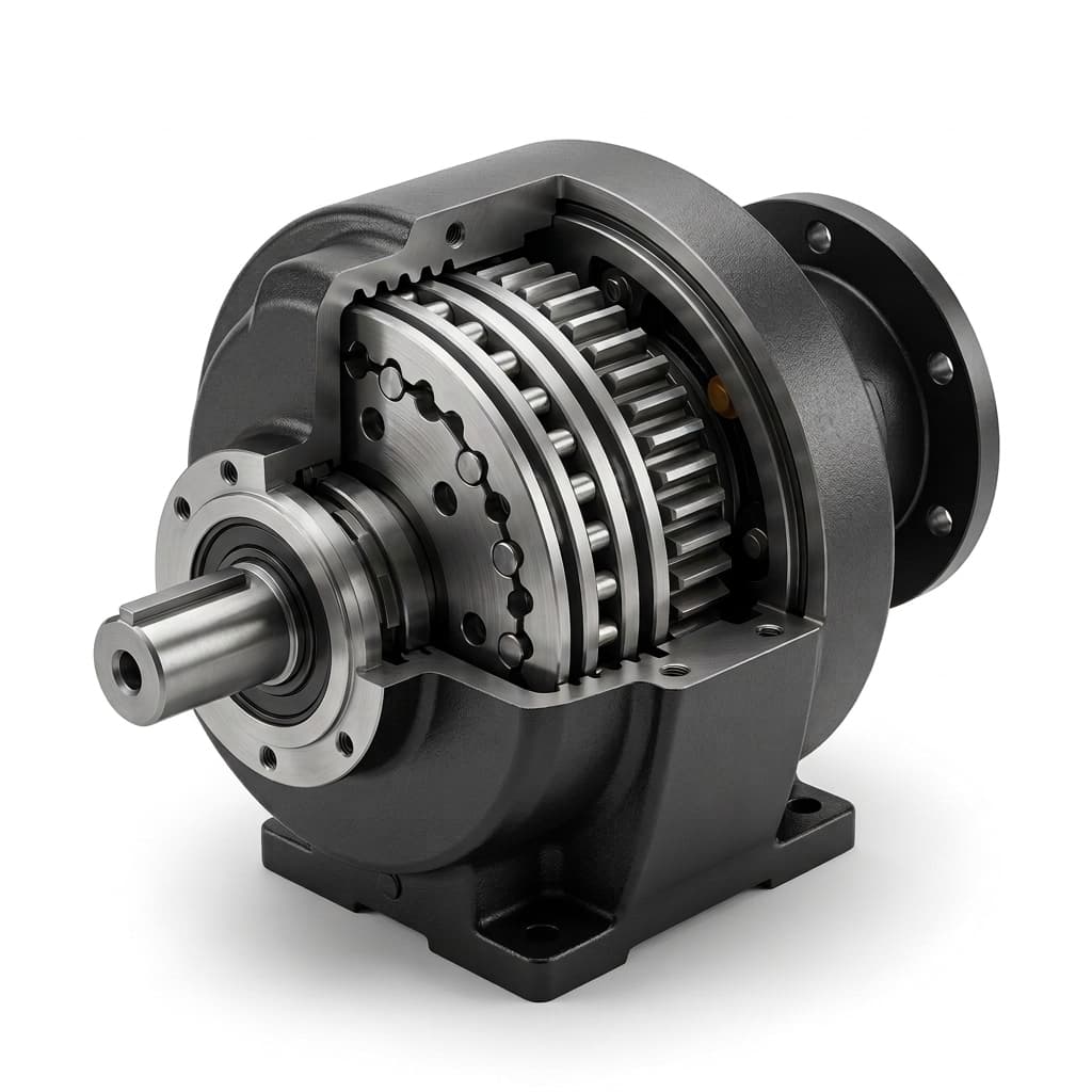
Cycloidal vs Planetary Gearboxes: Tradeoffs for Compact Robotics
An engineering comparison between cycloidal reducers and planetary gearboxes, covering backlash, torsional stiffness, load path, package size, and shock-load review.
Cycloidal vs Harmonic Drive for Robot Joints: Shock Overload, Torsional Wind-up, and Fatigue Life Tradeoffs
Cycloidal vs harmonic drive for robot joints: compare shock limits, torsional wind-up and fatigue life. Use the checklist to prepare your reducer RFQ.
How to Select the Right Cycloidal Reducer for AGV and AMR Drive Wheels
A highly technical sizing guide for OEM engineers selecting cycloidal reducers for Automated Guided Vehicles (AGVs). Includes torque formulas, radial load calculations, and duty cycle analysis.