
Cycloidal vs Harmonic Drive for Robot Joints: Shock Overload, Torsional Wind-up, and Fatigue Life Tradeoffs
Cycloidal vs harmonic drive for robot joints: compare shock limits, torsional wind-up and fatigue life. Use the checklist to prepare your reducer RFQ.
Published and reviewed: 27 October 2026. Scope: global OEM robot-joint selection, including industrial arms, humanoids and exoskeleton prototypes. This comparison is an engineering screening guide; it does not establish a product rating or validate a complete robot's safety.
Key Takeaways for Sourcing Engineers
For a cycloidal vs harmonic drive decision, compare two specific reducer configurations against the same joint duty cycle:
- Shock overload: obtain each model's permissible repeated-peak and momentary torque, event duration and event count. Neither mechanism has a universal overload multiplier.
- Torsional wind-up: compare measured torque-angle curves at the loads your joint actually uses. Zero backlash does not mean zero elastic deflection.
- Fatigue life: distinguish component rating life, gearbox service life and field MTBF. A flexing cup alone does not establish a replacement interval.
- Packaging: compare complete assemblies with equivalent output bearings, housings, brakes and interfaces, rather than a bare component set against a complete gearbox.
- Procurement: request the rating calculation, inspection method and sample acceptance plan before treating a lower unit price as a lower lifecycle cost.
Evaluating an existing joint? Start with the RFQ checklist in section 8 and request an engineering review using your current model and load profile.
Method and evidence limits: this article combines the manufacturer mechanism explanation and bearing-life scope listed in the references with an editorial selection matrix. The wind-up and cost examples are reproducible calculations using explicitly assumed inputs. They are not physical test results, supplier quotations or customer case studies. No matched-model endurance or collision-test dataset is presented, so this guide does not rank the two technologies by a fixed lifespan or shock margin.
1. Mechanical Operating Principles: Flexure and Cycloidal Contact
A strain wave gear uses a wave generator to deform a flexspline into engagement with a circular spline. In the common cup arrangement, the tooth-count difference produces the reduction. Harmonic Drive's mechanism explanation describes the three elements and their operation; the exact arrangement depends on the product family.
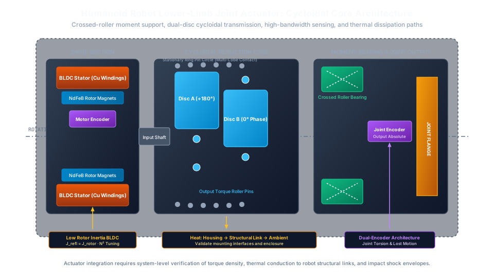
A cycloidal pin reducer uses an eccentric input to move lobed discs against a ring of pins or rollers. An output mechanism extracts the reduced rotation. Disc count, preload, output support and contact geometry vary by design; contact includes friction and should not be described as universally pure rolling.
Strain wave: motor -> wave generator -> flexspline/circular spline mesh -> output
Cycloidal:   motor -> eccentric -> disc/ring-pin contact -> output mechanism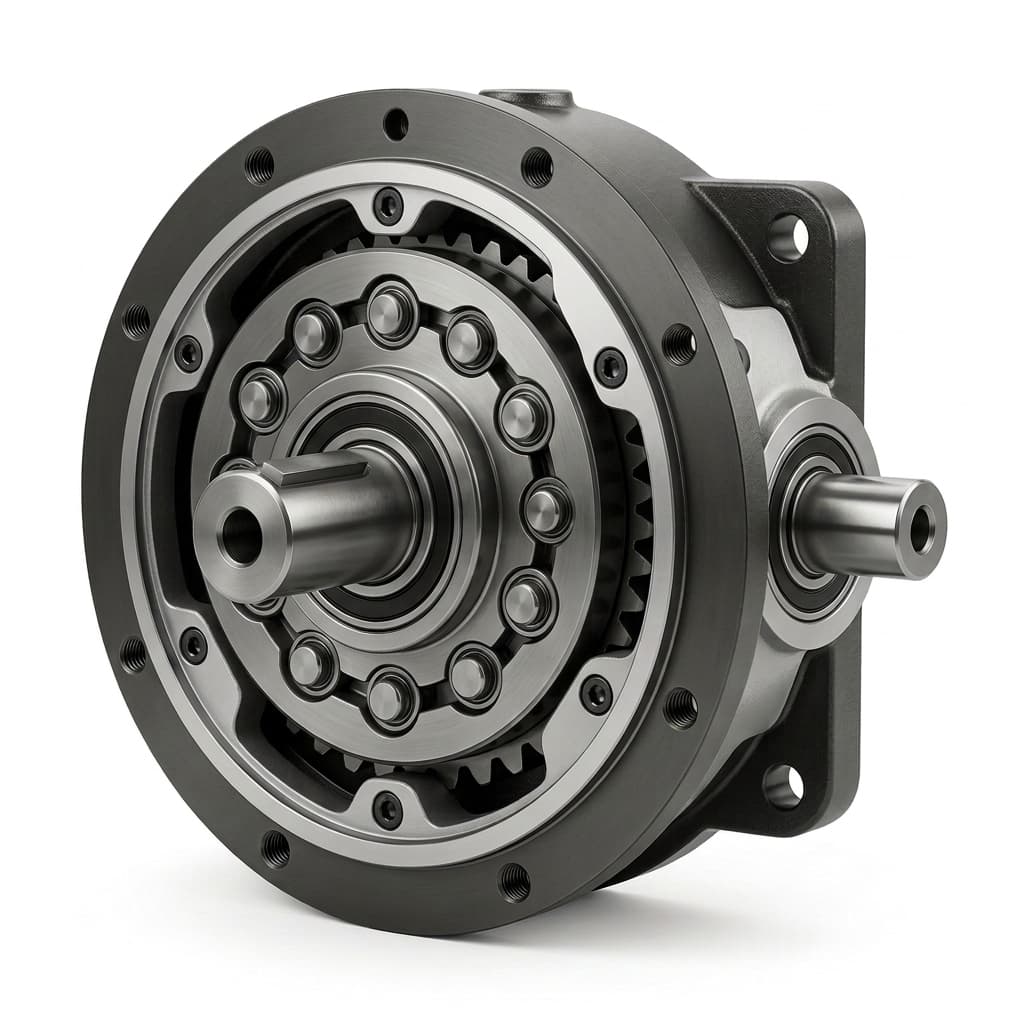
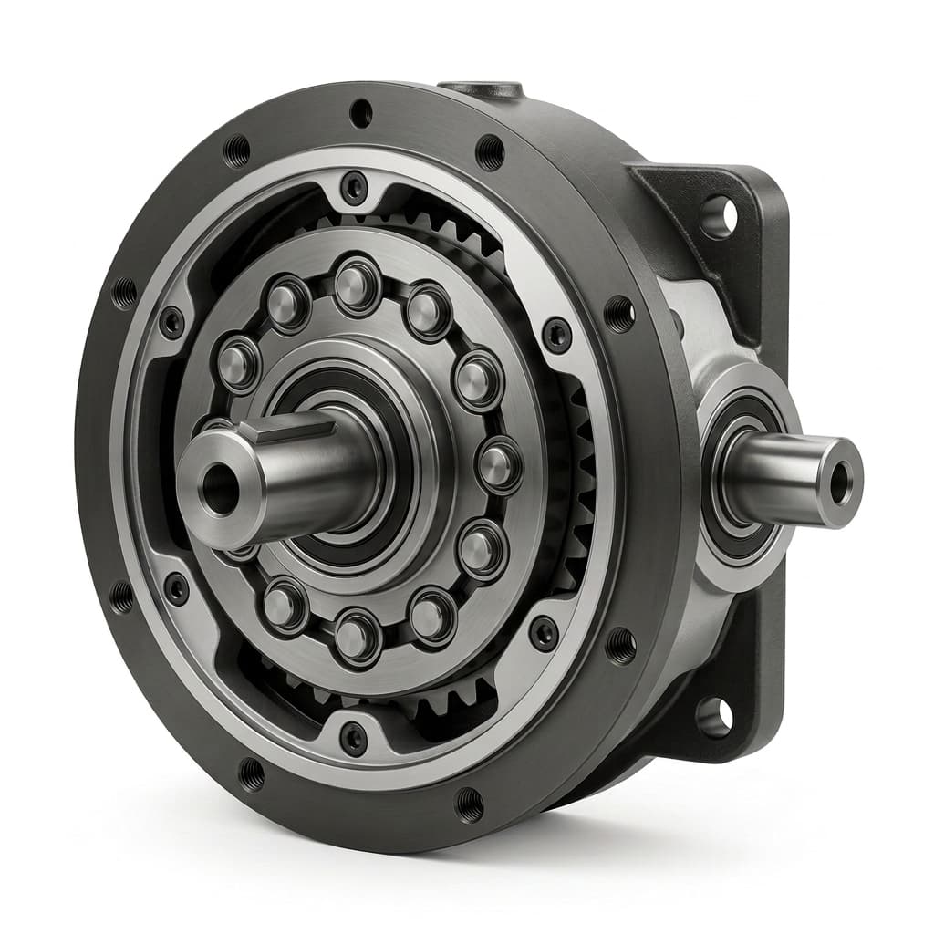
Illustrative reducer package showing the housing and output arrangement. This image is not a dimensioned drawing or evidence of shock capacity, stiffness or fatigue life; confirm internal geometry and interfaces from the selected model's drawings.
The practical question is how each complete assembly carries the required torque and external loads within your mass and envelope limits. A mechanism sketch cannot establish those ratings.
2. Shock Loads: Separate Repeated Peaks from Exceptional Events
Emergency braking, tool collisions and foot strikes can produce different torque histories. Record torque at the reducer output, rise time, duration, direction, speed and repetition count. Include the motor, brake, payload inertia and structural compliance in the load model; payload mass alone cannot predict a collision peak.
Ask both suppliers to distinguish:
- Continuous or duty-cycle operation: permissible torque and speed with the stated thermal and lubrication conditions.
- Repeated acceleration and braking: allowable peaks with an explicit duration and cycle limit.
- Exceptional events: any permitted momentary load, its event-count restriction and the required inspection afterward.
For strain wave designs, ask whether a ratcheting threshold is specified separately from permissible torque. Tooth skipping is not a routine torque-limiting function. If a suspected skip occurs, stop operation and obtain the manufacturer's inspection and replacement instructions; software re-homing cannot establish mechanical condition.
For cycloidal candidates, ask for limits on the discs, pins, eccentric bearings, output bearing, shaft and housing. Eliminating a flexspline does not eliminate overload damage or sudden failure. Do not infer that an advertised peak multiplier covers repeated foot strikes or every emergency stop.
Selection rule: accept a candidate only when the supplier's rating definitions cover your load history. An unknown peak duration or event count is an unresolved RFQ item, rather than an assumed pass.
3. Fatigue Life: Rating Life Is Not MTBF
Flexspline fatigue, tooth or pin damage, bearing fatigue, lubricant condition and mounting errors can all influence service life. Normal elastic flexing does not imply a universal 5,000–10,000-hour wear-out limit: the manufacturer's explanation states that flexspline stresses are designed below the endurance limit within catalogue ratings. That statement does not guarantee unlimited life for the assembled joint.
For rolling bearings, ISO 281:2007 defines basic rating life at 90% reliability for its stated bearing scope. It does not turn an individual bearing calculation into gearbox MTBF, and its scope excludes effects such as wear and corrosion. The familiar constant-load screening relationship is:
L10h = (C / P)^p × 1,000,000 / (60 × n)
C: bearing dynamic load rating; P: equivalent bearing load (same force units)
n: bearing rotational speed in rpm; p: 3 for balls, 10/3 for rollers
Use the bearing manufacturer's method for combined loads, oscillation, lubrication and contamination. Do not substitute output torque directly for bearing force, assume every bearing runs at output speed, or apply this formula directly to cycloidal disc/pin contacts without an applicable model.
To compare service-life proposals, give each supplier the same torque-speed-time spectrum, temperature, external loads, lubrication plan and required reliability. Request the limiting component and calculation basis. A 20,000-hour requirement is a design target until the selected assembly has supporting calculations and endurance evidence; it is not an inherent property of cycloidal gearing.
4. Torsional Stiffness and Hysteresis: Measure the Working Range
Torsional stiffness is the local slope of a torque-angle curve. Backlash describes clearance, while the measured reversal response can also include elastic deflection, friction and hysteresis. Both reducer families need a defined test method; neither a zero-backlash label nor a single high-load stiffness figure establishes low-load positioning performance.
Request a bidirectional torque-angle sweep with the input locked, a documented fixture stiffness, the actual preload and temperature, and the output bearing configuration used in the robot. Compare low-load reversal, gravity-loaded holding and acceleration loads separately. If a catalogue uses stiffness regions such as K1, K2 and K3, retain that supplier's region boundaries rather than applying universal percentages.
Worked wind-up example: assumed inputs, not a product benchmark
Suppose a candidate's local stiffness is 60 N·m per arc-minute, the applied torque change stays within that stiffness region at 30 N·m, and the effective arm length is 0.5 m:
Angular deflection = 30 / 60 = 0.5 arc-minute
Angular deflection in radians = 0.5 × π / (180 × 60) ≈ 0.0001454
Small-angle endpoint displacement = 0.5 m × 0.0001454 ≈ 0.073 mm
This is a static screening estimate for the reducer contribution only. It excludes link bending, bearing tilt, hysteresis, thermal drift and controller compensation. Use a measured curve for nonlinear regions. Verify settling time on the complete actuator with the intended inertia and control settings before promising a bandwidth improvement.
5. Engineering Comparison Matrix
These are comparison questions and design considerations, not technology-wide product specifications.
| Engineering parameter | Harmonic / strain wave candidate | Micro cycloidal candidate | Evidence required for selection |
|---|---|---|---|
| Transmission mechanism | Flexible spline and mating teeth | Eccentric disc and ring-pin contact | Model arrangement and load path |
| Shock overload | Check permissible peak limits and any separate ratcheting boundary | Check disc, pin, bearing and housing limits | Torque, duration, direction and permitted event count |
| Torsional wind-up | Compare the relevant torque-angle regions | Compare the measured curve with actual preload | Same fixture, temperature and torque range |
| Backlash and lost motion | Low clearance still permits elastic deflection | Preload can reduce clearance while affecting friction | Reversal torque, locked member and measurement method |
| Precision drift | Depends on loading, lubrication and wear | Depends on loading, lubrication and wear | Before/after endurance measurements with the same protocol |
| Fatigue and service life | Identify the limiting component under the duty spectrum | Identify the limiting component under the duty spectrum | Life calculation, reliability basis and endurance evidence |
| Output bearing | A component set may need separate support | Integrated support is configuration-dependent | Combined force and moment ratings, stiffness and mounting |
| Mass and envelope | Compact component sets merit review in distal joints | Include discs, eccentric support and complete housing | Complete installed mass and CAD envelope |
| Hollow bore and interfaces | Bore and mounting vary by family | Bore and mounting vary by family | Cable clearance, brake, encoder and fastener access |
| Backdrivability | Depends on ratio, friction, preload and attached motor | Depends on ratio, friction, preload and attached motor | Breakaway and running torque in the actual assembly |
| Temperature and grease | Confirm the chosen lubricant and operating conditions | Confirm the chosen lubricant and operating conditions | Thermal run, lubricant compatibility and service interval |
| Purchase and lifecycle cost | Quote the complete installed configuration | Quote the complete installed configuration | Same volume, inspection scope, maintenance and downtime assumptions |
6. Application Zoning: Shortlist by Axis Requirements
Humanoid lower limbs and cobot base or shoulder axes
Cycloidal candidates merit evaluation when measured shock exposure, output support or stiffness is a dominant constraint. Strain wave candidates remain eligible if their documented limits and the joint design cover the same loads. Foot-strike repetition and occasional trips require separate load cases; neither joint location nor robot mass establishes an automatic winner.
Use the humanoid robot joint reducer solution and collaborative robot joint reducer solution to frame the axis-specific RFQ. The harmonic drive alternative evaluation plan explains the baseline and sample-validation information to prepare.
Distal wrists, fingers and sensor axes
Strain wave component sets can be attractive where mass and envelope dominate. Compare the complete installed package and cable route against a compact cycloidal candidate. A low moving mass does not remove tool-collision loads, and gearbox backlash alone does not establish optical pointing accuracy.
Exoskeletons and hand-guided mechanisms
Prioritize measured breakaway torque, reflected inertia, power-off behavior and human interaction requirements. Neither transmission family guarantees easy backdriving or a safe release. The exoskeleton compact reducer solution is a starting point for defining that application review.
7. A 20,000-Hour TCO Sensitivity Calculation
Hypothetical budgeting example: the following USD amounts are assumed inputs, not quotations or observed failure records. Candidate A and B are not assigned to either transmission technology. Both use the same assumed maintenance schedule so that a lifespan advantage is not built into the result.
Assume 16 operating hours/day × 250 days/year × 5 years = 20,000 hours. Budget one planned replacement at 10,000 hours for each candidate as a purchasing scenario, not a predicted fatigue limit. Assume replacement labor is 2 hours × $150/hour and total lubrication expense is $80 for each candidate. Planned replacement happens during an existing shutdown, with no incremental line-stoppage charge in this example.
| Assumed cost input | Candidate A | Candidate B |
|---|---|---|
| Initial unit | $850 | $620 |
| One planned replacement unit | $850 | $620 |
| Planned replacement labor | $300 | $300 |
| Total lubrication budget | $80 | $80 |
| Incremental planned line stoppage | $0 | $0 |
| Subtotal before unexpected events | $2,080 | $1,620 |
For one additional unexpected replacement, assume 4 hours of line stoppage at $1,500/hour and 3 hours of repair/recalibration labor at $150/hour. The added event cost is the replacement unit price + $6,000 + $450: $7,300 for A or $7,070 for B. These are additive costs only if the event does not replace a planned service visit; otherwise adjust the schedule to avoid double counting.
B's base-case saving is $460. If B alone has one additional unexpected event, its total becomes $8,690, while A remains $2,080. This sensitivity shows why unsupported zero-failure assumptions can dominate a comparison. It predicts no event probability or technology advantage. Replace the unit prices, maintenance schedule and event counts with quotes and relevant operating records; add taxes, freight, validation and other installation costs for a purchasing decision.
8. Sourcing and Procurement RFQ Checklist
- Duty spectrum: output torque, speed, direction and duration for each operating segment; include gravity, acceleration and dwell. Do not use motor RMS torque alone as a gearbox fatigue calculation.
- Exceptional events: braking, collision or foot-strike torque history, rise time, duration and required lifetime event count; request the supplier's corresponding limit definition.
- Ratio and speed: required reduction, nominal and maximum input/output speeds, and any reversal or oscillation limits.
- External loads: radial force, axial force, overturning moment, payload offset and the proposed output bearing arrangement.
- Precision acceptance: backlash/lost-motion target, applied reversal torque, fixture stiffness, temperature, hysteresis and loaded deflection limits; agree on a repeatable measurement protocol.
- Mechanical interfaces: complete installed mass, OD, length, bore clearance, motor pilot, brake, encoder, output flange and fastener access; exchange controlled CAD revisions.
- Environment and maintenance: ambient and internal temperatures, sealing needs, contamination, lubricant compatibility, service interval and desired life/reliability basis.
- Commercial and validation scope: prototype quantity, production volume, quote inclusions, sample tests, acceptance criteria, inspection records and responsibility for engineering approval.
9. Frequently Asked Questions
Can a ratcheted harmonic drive be repaired or recalibrated in the field?
Re-homing restores a position reference; it does not establish that teeth or bearings are undamaged. Isolate a suspected overload and follow the exact manufacturer's inspection instructions. Repairability and component replacement depend on the model and damage assessment; this guide cannot establish a remaining safe operating life.
How does backdrivability compare between cycloidal and harmonic reducers?
Measure both candidates at the intended ratio, temperature, preload and speed, with the actual motor, seals and brake configuration. Ask for breakaway torque and running backdrive torque. A transmission label or reduction ratio alone cannot establish hand-guiding quality or power-off release behavior.
What is the difference between lost motion and backlash?
Backlash is clearance-related free motion on reversal. A supplier's lost-motion measurement can also include low-load compliance and hysteresis. Require the specified test torque, locked member, fixture and angular measurement procedure. A fixed percentage of rated torque is not a universal definition, and robot-level pose testing is not a substitute for a reducer reversal test.
Can a micro cycloidal reducer directly replace a harmonic drive cup set?
Treat the change as an integration review. Confirm the complete envelope, output support, input direction, ratio, mounting fits, brake, encoder, cable route and controller tuning. Matching torque and OD does not establish interchangeability. For a small envelope, review the ultra-micro cycloidal reducer against the current assembly's CAD and acceptance requirements.
How do temperature and grease affect preload and service life?
Material expansion, mounting fits, lubricant viscosity and internal heating can change friction and clearance in either design. Use the specified lubricant and run a thermal duty test at the intended ambient conditions. Do not assume all components share one expansion coefficient or that a higher-temperature grease is automatically compatible.
What safety factor should a robot joint emergency stop use?
There is no universal torque multiplier for every joint or reducer. Derive the braking load case, including inertia, brake timing, load path and repetition, then compare it with the supplier's applicable limits. Gearbox torque margin is one input to the complete machine's safety validation; it cannot establish safety compliance by itself.
10. References and Verifiable Sources
- Harmonic Drive LLC — strain wave gear principle. Manufacturer explanation of the mechanism and flexspline design conditions. Supports the architecture discussion; it does not establish the performance of every strain wave product or a matched cycloidal comparison.
- ISO 281:2007 — Rolling bearings: Dynamic load ratings and rating life. The public scope identifies the bearing-life basis and exclusions. It does not provide a complete reducer-life guarantee; use the applicable edition and manufacturer calculation for the selected bearing.
- Harmonic Drive LLC — catalogue access. Official catalogue entry point linked by the manufacturer's technology page. Use the selected series and revision to obtain model-specific ratings and drawings before an RFQ. This index is not evidence of a universal overload multiple or service-life advantage.
The first two source texts were reviewed on 27 October 2026. The catalogue entry point was identified in the manufacturer's navigation; no model catalogue or matched endurance dataset was independently reviewed for this article. Application recommendations and worked examples above are editorial screening judgments, not manufacturer approval.
Engineering Consultation and OEM Sample Sourcing
Prepare your current reducer model, motor drawing, torque-speed-time profile, exceptional-event loads and envelope constraints. Contact the Microcycloidal engineering team for a candidate and sample-validation review. Ask for the proposed configuration's rating basis, CAD, inspection method and sample acceptance plan before releasing a purchase order.
Author

Categories
More Posts
Micro Cycloidal Reducers for Surgical and Medical Robotics: Backlash, Torsional Rigidity, Cleanroom Sealing, and IEC 80601-2-77 Compliance
Select micro cycloidal reducers for surgical robotics: compare backlash, stiffness, thermal and sealing evidence, then prepare an application-specific OEM RFQ.
Cycloidal vs Planetary Gearboxes: Tradeoffs for Compact Robotics
An engineering comparison between cycloidal reducers and planetary gearboxes, covering backlash, torsional stiffness, load path, package size, and shock-load review.
Humanoid Robot Knee and Ankle Actuators: Cycloidal Reducer Selection for Foot-Strike Shock Loads, Reflected Inertia (J·N²), Backdrivability, and Sealed Limb Thermal Runaway
Select cycloidal reducers for humanoid knee and ankle joints: compare shock loads, reflected inertia and sealed-limb heat. Use the RFQ checklist to plan tests.