
Humanoid Robot Knee and Ankle Actuators: Cycloidal Reducer Selection for Foot-Strike Shock Loads, Reflected Inertia (J·N²), Backdrivability, and Sealed Limb Thermal Runaway
Select cycloidal reducers for humanoid knee and ankle joints: compare shock loads, reflected inertia and sealed-limb heat. Use the RFQ checklist to plan tests.
Published and reviewed: 9 November 2026. Scope: Global OEM engineering and procurement guide for selecting, sizing, and validating precision cycloidal reducers deployed in bipedal humanoid robot knee and ankle pitch/roll joints. Target readers include mechanical powertrain designers, robotic systems architects, motion control engineers, and procurement teams evaluating structural shock survivability, reflected rotor inertia, dynamic backdrivability, sealed thermal limits, and supplier quality gates.
Evidence and modeling boundary: This article combines first-principles screening calculations with the specific research and manufacturer references linked below. All numerical examples are hypothetical inputs, not measured Microcycloidal hardware results, supplier ratings, or proven safety margins. The cited legged-robot research concerns a quadruped; applying its design principles to humanoids requires validation. Complete joint qualification requires physical testing under the intended foot-strike profiles, thermal boundaries, and duty cycles. This guide does not establish robot safety compliance.
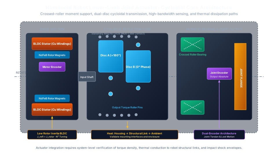
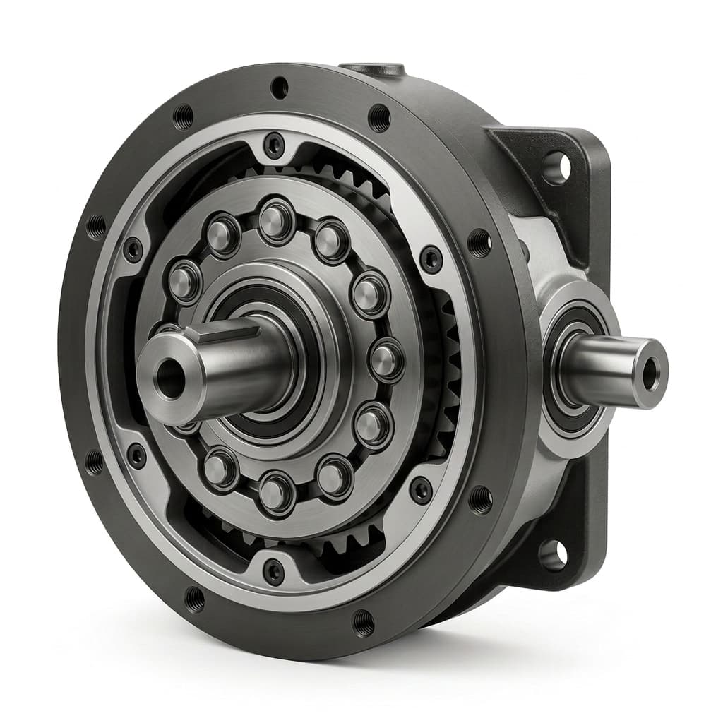
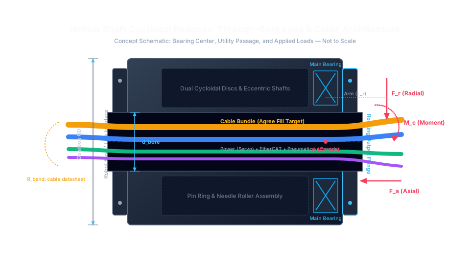
Illustration note: The schematic is a concept arrangement, not a manufacturing cross-section or dimensioned drawing. The gearhead image is a product illustration; neither image proves a shock rating, bearing specification, or drop-in fit.
Key Takeaways for Humanoid Powertrain Engineers and Sourcing Leads
Humanoid bipedal locomotion places harsh, conflicting demands on lower-limb rotary actuators. Unlike industrial articulated arms operating in rigid, predictable workspaces, humanoid knees and ankles interact continuously with unstructured ground environments. A successful actuator selection balances five physical constraints:
- Impact survival requires a defined load spectrum. Record torque, pulse duration, repetition count, joint pose, and the accompanying bearing loads. Cycloidal multi-pin engagement can be useful, but emergency overload capability is model-specific and does not establish repeated foot-strike fatigue life.
- Reflected inertia (J_refl = J_rotor * N^2) affects impact response. Increasing ratio can reduce holding-current demand while increasing output-referred rotor inertia. There is no universal ratio at which a joint becomes rigid; motor inertia, structural compliance, friction, and control limits must be evaluated together.
- Backdrivability requires controlled breakaway friction. Dynamic impedance control and safe environmental interaction rely on low joint mechanical impedance. While cycloidal drives offer high torque density, eccentric bearings and multi-lobe sliding contact create non-linear friction and torque ripple. Sourcing specifications must define maximum static breakaway torque and bidirectional backdriving resistance across the operating temperature range.
- Sealed leg fairings change the heat rejection boundary. Walking generates copper, iron, bearing, mesh, and lubricant losses. Internal convection and radiation still occur, but heat must ultimately leave through the enclosure or structural interfaces. Measure those paths rather than assuming the cavity is adiabatic or that a composite link is an effective heatsink.
- Ankle 2-DoF joints need a verified moment-load path. Single-leg stance generates combined radial, axial, and overturning loads. An integrated crossed-roller bearing is one compact option; adequately sized separate bearings or angular-contact arrangements are alternatives.
Sizing a humanoid bipedal knee or 2-DoF ankle actuator module? Review the procurement checklist in Section 8 and request an application sizing review with your dynamic gait load profiles, dimensional envelope, and chassis thermal boundaries.
1. Foot-Strike Dynamics: Ground Reaction Forces and Shock Torque Spikes
Ground reaction force (GRF) during foot contact is a key input to lower-limb sizing. Its peak and duration depend on terrain stiffness, foot compliance, landing velocity, gait, and control behavior. Do not infer a validated impact force from robot mass or step height alone. Use measured contact data or a validated multibody model to establish the design load spectrum.
Dynamic Impact Torque Formulation
For an initial one-axis envelope, engineers can separately screen contact moment and downstream inertial demand:
T_screen = abs(F_GRF_peak * L_effective) + abs(J_downstream * alpha_impact)Where:
F_GRF_peakis the peak impulsive ground reaction force [N].L_effectiveis the instantaneous perpendicular moment arm from the foot contact center of pressure to the joint axis [m].J_downstreamis the combined mass moment of inertia of the foot/shank structure downstream of the gearbox output [kg*m^2].alpha_impactis the transient angular deceleration resulting from rigid foot-ground collision [rad/s^2].
This magnitude sum assumes the terms reinforce each other. It is not a full inverse-dynamics equation: actual signs, gravity, coupled axes, and linkage geometry matter. If a simulation already outputs actuator joint torque including inertia, do not add the same inertia term again.
Illustrative Numerical Scenario:
Consider a 65 kg robot and assume, solely for screening, a peak GRF of 3.0 times body weight. This assumed multiplier is not a prediction for any particular curb height or gait:
F_GRF_peak = 3.0 * (65 kg * 9.81 m/s^2) = 1,913 NAssume effective perpendicular lever arms of 0.08 m (80 mm) at the ankle pitch axis and 0.14 m (140 mm) at the knee pitch axis. These must come from the actual pose and contact geometry; flexion angle alone does not determine them. Neglecting downstream inertia for initial contact-moment screening:
T_ankle_pitch = 1,913 N * 0.08 m = 153.0 Nm
T_knee_pitch  = 1,913 N * 0.14 m = 267.8 Nm
Against a hypothetical knee continuous requirement of 45 to 60 Nm, the 267.8 Nm contact moment is about 4.5 to 6.0 times that requirement. This comparison is not an allowable gearbox overload factor. If independently established downstream inertia is 0.30 kg*m^2 and angular deceleration is 150 rad/s^2, the additional magnitude is 45 Nm; the same-direction screening sum is 312.8 Nm. Specify event duration and repetitions before asking a supplier whether its reducer can tolerate that envelope.
Compare Model Ratings Before Choosing a Transmission
Transmission family alone does not predict service life. Compare actual candidate models at the same joint torque-speed spectrum, mass boundary, and support-bearing arrangement:
- Strain wave reducers: A flexspline provides compact reduction and low backlash. Evaluate repeated peak torque, momentary limits, stiffness, and flexspline fatigue using the selected model's data. Do not assign a universal failure multiplier to this family.
- Planetary gearheads: Ratio, stage count, tooth geometry, and support layout determine packaging and backlash. Request the configured assembly's peak-load and life data; neither rapid backlash growth nor excessive axial length follows automatically from the planetary architecture.
- Cycloidal reducers: An eccentric mechanism transfers load through multiple pin contacts. The Nabtesco RV product guide describes multi-pin engagement and model-limited shock capability. That industrial RV evidence does not qualify a miniature humanoid gearhead. Require model-specific pulse and fatigue records, including bearings, output pins, fasteners, and housing.
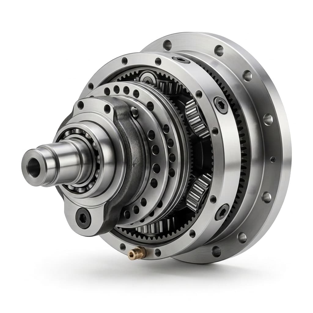
Product illustration for packaging discussions; it does not establish internal bearing construction or a verified impact rating.
2. Reflected Rotor Inertia (J·N²) and the Backdrivability Dilemma
A transmission must be selected together with its motor and controller. The MIT Cheetah proprioceptive-actuator study examines low gearing, backdrivability, and impact mitigation in a quadruped. It supports evaluating the whole actuator rather than choosing a humanoid ratio from a gearbox family name. Quasi-direct drive (QDD) describes a system approach, not a guaranteed property of every low-ratio cycloidal reducer.
The Physics of Reflected Rotor Inertia
Under an ideal rigid-ratio approximation, the output-referred rotating inertia includes:
J_reflected = J_rotor * N^2 + J_gearhead_output_equivalentWhere:
J_rotoris the rotational inertia of the motor rotor [kg*m^2].Nis the gear reduction ratio.J_gearhead_output_equivalentincludes the input shaft and other transmission components, each referred to the output through its own kinematics [kg*m^2]. Do not add raw input-side inertia without reflecting it, or count the input shaft twice.
The rotor contribution scales with N^2. Total joint response also includes link inertia, friction, compliance, and the drive's electrical behavior.
Numerical Evaluation: The Reflected Inertia Trade-Off
For a hypothetical motor with J_rotor = 1.2 x 10^-4 kg*m^2, compare three ratios while holding rotor inertia fixed. These are rotor-only calculations; transmission inertia is omitted. A real lower-ratio design may need a different motor, changing the result:
Scenario A (N = 16:1):
J_refl = (1.2 * 10^-4 kg*m^2) * (16)^2 = 0.0307 kg*m^2

Scenario B (N = 32:1):
J_refl = (1.2 * 10^-4 kg*m^2) * (32)^2 = 0.1229 kg*m^2  (4.0x increase)

Scenario C (N = 100:1):
J_refl = (1.2 * 10^-4 kg*m^2) * (100)^2 = 1.2000 kg*m^2  (39.1x increase)
Now examine what happens during the first 10 milliseconds of a heel strike, when the ankle joint is forced to rotate at an angular acceleration of alpha = 150 rad/s^2. The torque required purely to accelerate the motor rotor through the gearbox is:
T_accel = J_refl * alpha

Scenario A (N = 16:1):  T_accel = 0.0307 kg*m^2 * 150 rad/s^2 = 4.6 Nm
Scenario B (N = 32:1):  T_accel = 0.1229 kg*m^2 * 150 rad/s^2 = 18.4 Nm
Scenario C (N = 100:1): T_accel = 1.2000 kg*m^2 * 150 rad/s^2 = 180.0 Nm
Scenario C requires 180 Nm to produce the stipulated rotor acceleration. This is an inertial demand during motion, not a torque that appears before motion begins. Software cannot remove physical inertia, but actual contact response depends on compliance and achievable control bandwidth; sampling frequency alone does not establish that bandwidth. Scenarios A and B reduce this particular contribution without proving smooth backdrivability. Regeneration also needs a DC bus, battery, or braking circuit able to absorb returned energy.
Managing Cycloidal Breakaway Friction and Torque Ripple
Low reflected inertia alone does not guarantee high backdrivability. Cycloidal reducers feature several internal friction interfaces:
- The high-speed eccentric cam bearings.
- The rolling/sliding contact between the cycloid disc lobes and the ring pins.
- The output torque transmission roller pins sliding inside the disc drive bores.
Specify static breakaway torque (T_breakaway) and running backdriving torque (T_backdrive) at the joint output. Excessive interference, seals, or lubricant drag can mask small interaction torques. Test the assembly in both directions with the motor in explicitly defined states: disconnected, shorted, and enabled behavior can differ substantially.
Use application-derived acceptance limits:
- Shortlist ratios from the motor torque-speed envelope and the allowable reflected-inertia budget.
- For example, a 1.5 Nm breakaway target at 20°C is a proposed project requirement, not an industry-wide capability claim.
- Map running resistance versus output speed and temperature, with the final grease, seals, and bearing preload.
- Request vibration measurements for the complete eccentric assembly. Opposed discs can reduce imbalance but do not guarantee complete force and couple cancellation.
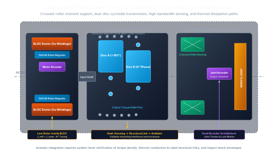
Engineering concept architecture of an integrated humanoid lower-limb rotary actuator pod, illustrating the structural crossed roller bearing, dual-disc cycloidal core, high-bandwidth sensing, and conductive heat dissipation paths.
3. Actuator Architecture Matrix: Comparing Lower-Limb Powertrains
Use this qualitative matrix to request comparable evidence. It is a screening framework, not a measured ranking; dimensions, mass, efficiency, and shock limits require candidate-specific data at the same operating points.
| Engineering metric | Lower-ratio cycloidal | Higher-ratio cycloidal | Strain wave drive | Planetary gearhead | Direct drive motor |
|---|---|---|---|---|---|
| Shock qualification | Require pulse and repeated-impact records | Same requirement; ratio is not a shock rating | Check flexspline and momentary limits | Check teeth, carrier, and support bearings | Check rotor attachment, bearings, and structure |
| Reflected rotor inertia | Calculate actual J_rotor * N^2 | Higher for the same rotor | Calculate actual motor and ratio | Include every configured stage | Actual rotor inertia; not zero |
| Backdrivability | Measure friction, seals, and preload | Measure reverse efficiency and breakaway | Measure hysteresis and reverse resistance | Measure stage and seal losses | Measure cogging, bearing drag, and drive state |
| Lost motion and backlash | Require bidirectional torque-angle curves | Same test at the selected preload | Distinguish backlash from elastic hysteresis | Include stage clearance stack | No gear backlash; structural compliance remains |
| Axial packaging | Check complete actuator envelope | Include input stage and output support | Include wave generator and bearings | Check configured stage arrangement | Check torque-driven motor diameter and cooling |
| Torsional stiffness | Use measured torque-dependent curve | Include housing and fastener compliance | Include low-torque windup | Include carrier and shaft compliance | Structure and controller determine response |
| Thermal losses | Map copper, mesh, drag, and iron loss | Check input-speed and lubricant limits | Map losses across load and temperature | Include all stages and seals | Copper, iron, windage, and bearing losses remain |
| System mass | Include motor, bearing, encoder, brake, and housing | Use the same mass boundary | Use the same mass boundary | Use the same mass boundary | Compare complete assembly at the same duty |
Sourcing Implications of the Comparison
A lower-ratio cycloidal candidate is useful when its documented load capacity, friction map, and package fit the project. It is not automatically the optimum solution. Lower ratio can increase the required motor torque and copper losses; higher ratio can increase rotor-reflected inertia. Direct drive eliminates gear mesh but still has finite inertia and losses. Strain wave and planetary candidates should remain in consideration when their measured system performance meets the same requirements.
If supplier proposals use different mass boundaries or test conditions, request a sizing review with a common comparison sheet. Resolve missing data before treating a brochure advantage as a purchase decision.
4. Humanoid Lower-Limb Joint Duty Spectrum and Failure Modes
Build the duty spectrum around knee and ankle axes rather than copying torque ranges from an unrelated robot. Record the sign and timing of torque and speed together: average torque multiplied by average speed does not generally equal average power. For a parallel ankle, transform the foot wrench through the linkage Jacobian at each pose before sizing either actuator.
| Load case | Required input | Reducer or system check | Evidence to request |
|---|---|---|---|
| Knee stance and crouch | Holding torque, duration, duty fraction | Copper heating at low or zero speed | Current-temperature trace with final mounting |
| Knee swing reversal | Speed, acceleration, rotor and link inertia | Repeated acceleration torque and input-speed limit | Synchronized torque-speed cycle |
| Knee stumble or landing | Contact moment, pulse shape, event count | Repeated and emergency peak capacity | Shock test plus post-test lost motion |
| Ankle pitch push-off | Torque-speed trajectory and foot lever arm | Mechanical power and thermal duty | Loaded efficiency map and endurance record |
| Ankle roll on uneven ground | Full force/moment vector and offsets | Bearing loads, flange and housing deflection | Combined-load calculation and mounted test |
| Powered-down or faulted contact | Drive state, brake behavior, external moment | Backdrive resistance and safe system response | Documented fault-state test procedure |
Separate normal cyclic operation, repetitive peaks, and rare emergency events. A motor duty designation does not certify a gearbox shock capacity or fatigue life. Ask for the supplier's rating definitions, permitted cycles, lubrication assumptions, mounting stiffness, and post-test acceptance criteria. For procurement, an unspecified rating is an unresolved item, even when its headline torque exceeds the screening calculation.
5. Thermal Runaway in Sealed Limb Cavities: Power Loss and Conduction Modeling
A sealed limb can overheat without exhibiting true thermal runaway. Runaway refers to positive feedback in which losses grow with temperature faster than heat rejection can stabilize them. For example, winding resistance rises with temperature; at controlled torque and approximately constant current, copper heating rises. Whether the actuator reaches a safe equilibrium requires a measured thermal model, not a fixed walking-time prediction.
Actuator Power Loss Formulation
For balanced three-phase sinusoidal currents, use actual per-phase RMS current and per-phase winding resistance at operating temperature:
P_copper = 3 * I_phase_rms^2 * R_phase(T)
P_out = abs(omega_out * T_out)
P_gear = P_out * (1 / eta_total - 1)   [motoring, nonzero output power]
P_heat = P_copper + P_gear + P_iron + P_other
Here eta_total is the measured overall gearhead efficiency at that operating point, including its bearing, seal, and churning losses. Do not add omega_in * T_no_load again when those losses are already included. If current is expressed as phase peak rather than RMS, the copper-loss coefficient becomes 1.5; a controller's q-axis current convention must be checked before either expression is used. Terminal line-to-line resistance also differs from per-phase resistance, depending on winding connection.
At zero output speed the efficiency expression cannot capture holding-current heat; calculate copper loss directly. At very light load, use measured drag or a loss map. Regenerative operation needs its own directional efficiency data and electrical energy path. The maxon Formulae Handbook, Chapter 9 provides the general loss and thermal-resistance framework; the following values are our illustrative assumptions, not its product data.
Worked Thermal Balance Example
Assume one steady motoring operating point: input speed 2,500 rpm, ratio 25:1, output speed 100 rpm, and output torque 55 Nm. Assume per-phase RMS current 14.5 A, per-phase winding resistance 0.28 Ohms at 80°C, and total gearhead efficiency 0.91. These independent illustrative inputs are not a validated motor operating point; a real design must reconcile them with torque constant, voltage, and current limits.
P_copper = 3 * (14.5 A)^2 * 0.28 Ohms = 176.6 W
omega_out = 100 * 2 * pi / 60 = 10.472 rad/s
P_out = 10.472 * 55 = 576.0 W
P_gear = 576.0 * (1 / 0.91 - 1) = 57.0 W
P_heat_partial = 176.6 + 57.0 = 233.6 W
The partial heat estimate is 233.6 W, before iron loss and other losses outside the gearhead efficiency boundary. This is not an average walking loss. Integrate instantaneous losses over the full gait cycle, including stance, swing, reversal, and regeneration, to estimate that quantity.
For an initial lumped thermal screen:
C_thermal * dT/dt = P_heat(T) - (T - T_ambient) / R_thermal
T_steady = T_ambient + P_heat * R_thermal   [constant-loss approximation]
If a project selects an 80°C casing target and 35°C ambient boundary, the illustrative partial loss alone requires total casing-to-ambient resistance no greater than (80 - 35) / 233.6 = 0.193 K/W. Additional losses reduce the allowable resistance. This is an early feasibility check; winding-to-case gradients and multiple heat sources require a multi-node model. An 80°C casing target is not a Class F insulation compliance statement. Without thermal capacitance, measured resistances, and component limits, no defensible prediction can be made that a sealed joint reaches a particular temperature after 20 or 30 minutes.
Engineering Mitigations for Sealed Limbs
- Characterize structural conduction: Test the mounting flange, contact pressure, interface thickness, link material, and final external enclosure. Thermal-interface conductivity alone does not determine interface resistance. Composite links can conduct very differently along and across fibers.
- Validate lubricant and fill: Follow the selected reducer manufacturer's grease type, quantity, orientation, and speed instructions. A universal 15%–25% fill rule or a thinner base oil can compromise lubrication. Verify drag and wear over the intended temperature range.
- Sense and derate: Measure winding and gearhead temperatures near relevant hotspots, validate sensor lag, and set thresholds from the actual winding, magnet, grease, bearing, seal, and encoder limits. Implement torque/speed derating and a system-tested controlled stop.
Track lubricant condition and clearance changes after thermal cycling. Magnet demagnetization depends on grade, magnetic circuit, and operating point; it cannot be inferred from a single generic temperature. Differential expansion can alter preload in either direction, so confirm the assembled joint rather than predicting seizure from material names alone.
6. Tilting Moment Capacity: Output Support in 2-DoF Ankles
Single-leg support on uneven terrain creates combined loads at an ankle bearing. Resolve forces into the selected bearing's coordinate frame first. A ground-vertical force is not automatically an axial bearing load when the rotary joint axis is horizontal.
Calculating Overturning Tilting Moments
Start from the vector moment M = r × F about the bearing center. For one selected moment component, a conservative planar magnitude sum can be written:
M_screen = abs(F_1 * d_1) + abs(F_2 * d_2)Assume two force components have reinforcing moments about the same assessed axis: 220 N at 0.085 m and 650 N at 0.045 m. Then:
M_screen = 220 * 0.085 + 650 * 0.045 = 47.95 NmThe number is a hypothetical load case, not the moment implied by a particular slope. If the moment vectors oppose or act about different axes, use their actual vector combination. Separate drive-axis torque from the bearing's overturning moment; they are not interchangeable catalogue ratings. The original angular-contact-bearing arrangement in the Nabtesco guide also demonstrates why crossed rollers are not mandatory for every cycloidal architecture.
Bearing and Flange Acceptance
Crossed-roller bearings offer compact combined-load support, but suitably arranged angular-contact pairs or external supports may also meet the design requirements. Compare the complete support system:
- Combined load and life: Give the supplier simultaneous radial force, axial force, moment, oscillation angle, event counts, and mounting stiffness. Request both static-load margin and the appropriate fatigue-life assessment.
- Preload and friction: Obtain the actual manufacturer's clearance and preload definitions. Labels such as P0 or C1 cannot be treated as universal preload grades across bearing families. Measure mounted friction cold and hot.
- Deflection and runout: Derive required moment stiffness from allowable foot deflection and required runout from encoder, seal, and flange interfaces. Specify the load and mounting conditions for each acceptance measurement instead of adopting an unsupported universal stiffness range.
7. Dynamic Compliance Sensing: Dual Encoders vs Current-Based Torque Estimation
Torque feedback must be evaluated against bandwidth, latency, friction, and calibration requirements. Neither a fast current sample nor a high encoder bit count directly proves accurate joint torque sensing.
Architecture 1: Motor Current-Based Torque Estimation
A first-order output estimate is:
T_joint_est = N * K_t * I_q - T_loss_output - J_rotor * N^2 * alpha_outUse a torque constant K_t consistent with the controller's current convention. T_loss_output represents output-referred mechanical losses; do not subtract them again if an efficiency model already includes them. The equation omits transmission inertia and other dynamics and must be expanded for the actual joint. Current can be a useful sensing input, but friction near reversal and acceleration torque can obscure external contact torque. Validate error against a reference transducer through cold starts, warm operation, and load reversals. Do not assume a generic percentage accuracy.
Architecture 2: Dual-Encoder Deflection Sensing
A synchronized input encoder and output encoder can estimate elastic windup:
delta_theta = theta_in / N - theta_out - theta_offset
T_joint_est = calibrated_torque_map(delta_theta, temperature, direction, history)
Account for ratio sign, angular unwrapping, encoder alignment, latency, lost motion, and hysteresis. A constant stiffness multiplier is appropriate only within a validated region of the torque-angle curve. High mechanical stiffness can make the measurable deflection very small; encoder accuracy, mounting eccentricity, and synchronization error may then dominate quantization resolution.
Encoder disagreement can be a diagnostic signal, but it does not provide guaranteed instant wear detection, a certified safety function, or proof that the robot can stop without falling. Set fault thresholds and validate the complete fault response at system level. If neither estimator achieves the required force-control accuracy, consider a calibrated torque sensor or a deliberately compliant sensing element.
8. Sourcing & Procurement RFQ Checklist for Humanoid Joint Reducers
Send the same requirement sheet to each supplier and distinguish a target, a documented rating, and a verified result. Use this checklist to close gaps before prototype purchase:
- 1. Envelope and mass: State maximum diameter, axial length, cable bore, interfaces, and complete actuator mass boundary, including motor, brake, bearings, and housing.
- 2. Joint duty and shocks: Supply synchronized torque-speed-time data, repetitive peaks, emergency pulse duration, event counts, and simultaneous bearing loads. A hypothetical 350 Nm for 10 ms is an RFQ input only, pending application validation.
- 3. Ratio and inertia: Request actual rotor inertia, transmission inertia with its reference shaft, candidate ratios, and input-speed limits. Calculate output-referred inertia for each complete assembly.
- 4. Backdrivability: Define project-specific breakaway and running-resistance limits, measurement location, rotation directions, temperature range, final seals, lubrication, and motor-drive state.
- 5. Stiffness and lost motion: Require bidirectional torque-angle curves, test load range, fixture stiffness, temperature, hysteresis definition, and acceptance after endurance testing.
- 6. Output support: Give bearing-coordinate forces and moments, offsets, oscillation duty, and required life. Ask for static and fatigue checks, actual preload specification, mounted runout, and flange deflection.
- 7. Thermal boundary: Define ambient and enclosed-cavity conditions, mounting contacts, cooling paths, allowable component temperatures, sensor locations, and derating behavior. Request a trace through thermal equilibrium or the agreed duty duration.
- 8. Lubrication and seals: Obtain manufacturer-approved grease, fill quantity, service interval, orientation limits, seal compatibility, and measured drag. An ingress-protection claim needs a tested assembly boundary and does not establish low friction.
- 9. Vibration and balancing: Request residual-unbalance or vibration acceptance for the actual eccentric mechanism, full speed range, and mounted actuator. Agree on a suitable test method rather than copying an arbitrary balance grade.
- 10. Quality and release: Require lot traceability, material and heat-treatment records for specified parts, critical-dimension reports, a sample validation plan, and explicit post-shock criteria for backlash, friction, noise, and leakage.
Release decision: Keep a candidate conditional if shock fatigue, thermal equilibrium, or backdrive data are missing. A supplier statement of peak torque alone is insufficient to close those items. Start with the prototype validation support scope to agree on samples and acceptance records; production release still requires the OEM's system-level review.
9. Frequently Asked Questions (FAQ)
Is a cycloidal reducer always better than a strain wave drive for humanoid knees and ankles?
No. Multi-pin load sharing makes cycloidal reducers worth evaluating for impact-sensitive joints, but the specific model must meet repeated-load, friction, mass, and thermal requirements. Compare emergency limits separately from fatigue life. A strain wave candidate that passes the same duty and qualification tests should not be rejected on family name alone.
What gear reduction ratio is ideal for a humanoid knee or ankle?
There is no universal ideal ratio. Start with the required output torque-speed cycle, available motor torque constant and current, rotor inertia, bus voltage, and cooling boundary. The 16:1, 32:1, and 100:1 calculations above isolate inertia scaling for one assumed rotor; they are not an approved ratio range for all humanoids. Recalculate if changing ratio also changes the motor.
How do engineers prevent overheating or thermal runaway inside sealed leg fairings?
Measure losses and heat rejection with the final enclosure and mounting interfaces. Establish winding, gearhead, magnet, seal, and sensor limits from the selected components, then validate sensor lag and derating. Use manufacturer-approved lubricant quantity. A casing temperature target alone does not establish winding insulation compliance, and overheating is not automatically thermal runaway.
How should cycloidal backdrivability be tested for impedance control?
Measure output breakaway torque in both directions and running resistance across the relevant speeds, temperatures, and load conditions. Document the motor-drive state and include production seals and preload. Compare the measured resistance and hysteresis against the smallest interaction torque the controller must resolve. Encoder resolution and low ratio alone do not establish adequate force-control accuracy.
Can a single cycloidal gearhead actuate both ankle pitch and roll?
One independent rotary input cannot provide two independently controlled output degrees of freedom. Serial or parallel two-axis ankle mechanisms typically use two independent actuators. In a parallel linkage, actuator loads depend on pose and the linkage Jacobian; neither actuator necessarily sees the full foot moment or a constant share of it. Size the support bearings separately from drive torque.
Do two cycloidal discs cancel all eccentric vibration?
Opposed discs can reduce selected imbalance forces when masses, eccentricities, and phasing are controlled. They do not automatically cancel every rotating couple, tolerance effect, or assembly resonance. Request residual vibration measurements through the actual speed range and mounting conditions. A single-disc architecture may also use other balancing measures; disc count alone is not a qualification result.
10. References and Verifiable Sources
- Wensing et al. — Proprioceptive Actuator Design in the MIT Cheetah: Impact Mitigation and High-Bandwidth Physical Interaction for Dynamic Legged Robots. Author manuscript hosted by MIT, published in IEEE Transactions on Robotics (2017). Supports the relationship between actuator design, backdrivability, and impact response. This is quadruped research, not certification of humanoid cycloidal hardware.
- Nabtesco — Precision Reduction Gear RV product guide. Manufacturer primary source; see the pin-and-gear and integrated outer-load-support discussions (printed pages 7–8). Documents its RV architecture and qualified catalogue claims; these are not transferable ratings for Microcycloidal products or all miniature reducers.
- maxon academy — Formulae Handbook, Chapter 9: Thermal behavior. See printed pages 47–49 for heat sources, input/output efficiency conversion, thermal resistance, and thermal time constants. Its motor notation must be reconciled with the actual winding and drive conventions.
Source review: Reviewed 9 November 2026. The links above support the stated design principles and explicitly identified manufacturer context. The numerical screening examples in this guide are independently disclosed assumptions, not measured performance or values claimed by those sources. No cited source establishes a universal humanoid shock multiplier, optimum ratio, grease fill, or safe walking duration. Revisit the calculations when motor, ratio, lubricant, enclosure, gait, or supplier revision changes. Physical impact, endurance, and thermal tests remain necessary before release.
Engineering Consultation and Humanoid Powertrain Sourcing
Designing a next-generation bipedal humanoid robot, quadruped platform, or dynamic legged actuator? Bring your envelope dimensions, dynamic gait torque profiles, impact shock estimates, and chassis thermal constraints to our engineering team. Contact the Microcycloidal technical sales team for an actuator sizing review and prototype quotation.
Explore our specialized humanoid robotics components and engineering support resources:
- Humanoid robot joint cycloidal reducer application solutions
- Compact humanoid cycloidal reducers for high-torque robotic limbs
- Flat pancake cycloidal reducers for ultra-compact joint packaging
- Low-backlash cycloidal drives for precision motion control
- Prototype validation, hysteresis testing, and shock load qualification
- Design for Manufacturing (DFM) support for custom actuator component sets
Author

Categories
More Posts
Micro Cycloidal Reducers for Surgical and Medical Robotics: Backlash, Torsional Rigidity, Cleanroom Sealing, and IEC 80601-2-77 Compliance
Select micro cycloidal reducers for surgical robotics: compare backlash, stiffness, thermal and sealing evidence, then prepare an application-specific OEM RFQ.
Cycloidal vs Harmonic Drive for Robot Joints: Shock Overload, Torsional Wind-up, and Fatigue Life Tradeoffs
Cycloidal vs harmonic drive for robot joints: compare shock limits, torsional wind-up and fatigue life. Use the checklist to prepare your reducer RFQ.
Hollow Shaft Cycloidal Reducers for Robot Joints: Through-Bore Sizing, Cable Routing, and Tilting Moment Bearing Capacity
Size hollow shaft cycloidal reducers for robot joints: check cable clearance, bend limits, and tilting moment capacity. Prepare your RFQ for engineering review.