
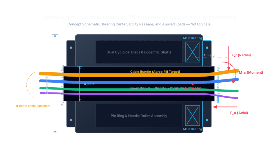
Hollow Shaft Cycloidal Reducers for Robot Joints: Through-Bore Sizing, Cable Routing, and Tilting Moment Bearing Capacity
Size hollow shaft cycloidal reducers for robot joints: check cable clearance, bend limits, and tilting moment capacity. Prepare your RFQ for engineering review.
Published and reviewed: 29 October 2026. Scope: global OEM hollow shaft cycloidal reducer selection for robot joints, collaborative robot arm packaging, continuous rotary indexers, and machine automation tooling heads requiring internal through-bore routing. This guide provides an engineering sizing methodology; it does not replace model-specific supplier qualification or machine-level safety risk assessments.
Evidence boundary: The calculations below are reproducible design examples, not measured product performance or customer test results. Fill targets, loads, and candidate ratings are explicit assumptions. Obtain cable-specific motion limits and reducer-specific load ratings before approving a design.
Key Takeaways for Sourcing Engineers
Specifying a hollow shaft cycloidal reducer (through-bore cycloidal gearbox) requires balancing internal harness volume against external load-carrying capacity:
- Through-bore sizing: This guide uses 40% electrical-only fill and 30% mixed cable/hose fill as initial screening assumptions, not universal industry limits. Connector clearance, separators, sleeves, and harness motion can require a larger aperture.
- Dynamic cable fatigue: Use the exact cable and hose datasheets for repeated bending, torsion, temperature, and cycle-life limits. A cable rated for a drag chain is not automatically qualified for robot-joint twisting.
- Tilting moment and stiffness: Check radial, axial, and overturning loads together. A permissible moment rating alone does not establish bearing life or tool-tip accuracy.
- Internal heating: Estimate conductor losses and measure temperatures with the enclosed harness operating. There is no universal temperature-rise allowance or required seal material for all hollow joints.
- RFQ procurement gate: Agree bore clearance, runout datums, edge treatment, combined-load limits, and stiffness acceptance criteria before freezing CAD models.
Evaluating a new hollow joint or tooling head? Start with the RFQ checklist in Section 7 and request an engineering application review with your load spectrum and cable bundle dimensions.
1. Mechanical Operating Principles: Central Through-Bore Kinematics
A hollow shaft cycloidal reducer provides a central passage for utilities that would otherwise need routing around the joint. This can reduce external dress-pack swept volume, but a hollow bore does not itself prevent cable twisting or permit unlimited rotation. The motor, input gearing, and eccentric drive must leave the required passage clear.
Illustrative Center-Thru Multi-Crank Architecture:
Motor -> Input Stage -> Synchronized Peripheral Crankshafts -> Cycloidal Discs -> Pin Ring Housing -> Main Bearing -> Output Flange
[Clear central passage: usable diameter depends on the selected assembly and installed sleeve]
To maintain an open center, the drive arrangement must keep the eccentric shafts clear of the utility passage. Review the internal layout and motor integration separately:
- Multi-crank cycloidal layout: Synchronized peripheral eccentric shafts drive the cycloidal discs while retaining a central opening. Confirm the input gear arrangement, shaft count, and through-tube interface on the selected model's section drawing.
- Off-axis input integration: An offset motor can drive the reducer through an additional gear or belt stage. Include that stage's clearance, compliance, tensioning, and service access in the joint envelope; an offset motor is not a separate guarantee of bore size or backlash.
The Nabtesco cycloidal gear portfolio identifies RV-C and RD-C as hollow-shaft families. This establishes available architectures, not interchangeability with a Microcycloidal model. Check whether the installed sleeve is fixed or rotating and how it isolates the harness from moving components.
2. Through-Bore Sizing: Cable Fill Factor, Dynamic Bend Radius, and Service Margins
Selecting the bore inner diameter (d_bore) from the static bundle diameter alone can overlook connector installation, cable migration, and strain relief. Clearance arithmetic is a first screening step; check the complete motion envelope before releasing the joint.
Cable Fill Factor Formulation
Cables routed through an oscillating joint can migrate, twist, and rub. For the examples here, use a provisional fill target of 40% for electrical-only bundles or 30% with hoses. These are design assumptions for reserving space, not a published cabling standard or a cable-life guarantee. Apply any stricter harness supplier limits and include the space occupied by liners and separators:
F_fill = ( Σ [ (π / 4) × d_i^2 ] ) / [ (π / 4) × d_bore^2 ]
F_fill ≤ F_target  (0.30 or 0.40 in this guide's examples)
Where:
F_fillis the cross-sectional bundle fill factor.d_iis the outer diameter of each individual cable, hose, or wire in the bundle.d_boreis the minimum usable clear diameter after installing sleeves and protective components.
Solving for the required minimum through-bore diameter:
d_bore ≥ √[ (1 / F_fill) × Σ (d_i^2) ]Worked Example:
A 6-axis cobot wrist requires passing through the J4-J6 hollow reducers:
- 1× Motor power & brake cable (OD = 9.2 mm)
- 1× 24V DC logic & I/O cable (OD = 6.5 mm)
- 1× Cat6A industrial shielded Ethernet cable (OD = 7.8 mm)
- 2× Pneumatic polyurethane air tubes (OD = 6.0 mm each)
Calculate sum of squared diameters:
Σ (d_i^2) = (9.2)^2 + (6.5)^2 + (7.8)^2 + 2 × (6.0)^2
Σ (d_i^2) = 84.64 + 42.25 + 60.84 + 72.00 = 259.73 mm²
With pneumatic lines included, apply the conservative 30% fill factor (F_fill = 0.30):
d_bore ≥ √[ 259.73 / 0.30 ] = √[ 865.77 ] ≈ 29.42 mm
Procurement decision:
Shortlist a model with at least 32 mm or 35 mm usable ID, subject to connector clearance.
A 25 mm bore gives 41.6% fill, exceeding this example's 30% target.
This flags a packaging review; it does not predict a specific failure or cycle life.Dynamic Bend Radius and Torsional Twist Rules
Obtain separate repeated-bending and torsion ratings for every cable and hose. Record the exact part number, allowed bend radius, twist per active metre, temperature, cycle count, and combined-motion test conditions. Ethernet performance must also be qualified during motion; electrical continuity alone is insufficient.
For a hypothetical cable whose supplier permits ±180° per metre under the intended duty, a joint moving ±270° from a neutral harness position requires:
L_twist ≥ θ_max / q_allow
L_twist ≥ 270° / (180°/m) = 1.5 m
L_twist is the free length that actually shares the twist, not the full cable run including clamped sections. This is a uniform-twist screening calculation; local strain relief and bends can concentrate strain. The 180°/m value is an example input, not a generic robotic cable limit. Check adjacent axes acting on the same harness and verify both extreme poses in a motion test.
If finite travel cannot be accommodated, review a torsion-rated harness, altered routing, or an electrical slip ring and rotary fluid union. For continuous rotation, check current, bus protocol/data rate, pressure, speed, and service-life ratings of those rotary interfaces.
Cable & Hose Screening Matrix across Example Bore Diameters
These are calculated passage areas, not standardized product frames or verified payload classes. Values are rounded; both columns use the provisional fill assumptions above. The example bundle occupies approximately 204.0 mm² of cross-sectional area.
| Usable bore ID | Gross bore area | Area at 30% fill | Area at 40% fill | Example bundle fill | Decision against 30% target |
|---|---|---|---|---|---|
| 20 mm | 314.2 mm² | 94.2 mm² | 125.7 mm² | 64.9% | Exceeds target |
| 32 mm | 804.2 mm² | 241.3 mm² | 321.7 mm² | 25.4% | Area check passes; verify connectors and motion |
| 45 mm | 1,590.4 mm² | 477.1 mm² | 636.2 mm² | 12.8% | Area check passes; verify connectors and motion |
| 60 mm | 2,827.4 mm² | 848.2 mm² | 1,131.0 mm² | 7.2% | Area check passes; verify connectors and motion |
| 80 mm | 5,026.5 mm² | 1,508.0 mm² | 2,010.6 mm² | 4.1% | Area check passes; verify connectors and motion |
| 110 mm | 9,503.3 mm² | 2,851.0 mm² | 3,801.3 mm² | 2.1% | Area check passes; verify connectors and motion |
A passing area check does not confirm that the largest connector fits. Record its diagonal envelope, strain-relief diameter, installation sequence, cable separation requirements, and the minimum passage at every adapter and seal carrier. Bore diameter also does not define the available bend radius outside the reducer.
3. Tilting Moment Capacity and Main Bearing Architecture
Determine whether the reducer’s integrated output bearing supports the downstream arm and tooling or whether an external bearing carries some of the load. Bearing arrangement and load sharing must be explicit in the joint model.
Cantilevered tooling, heavy grippers, and deceleration create tilting moments (M_c). Check bearing load capacity and angular deflection separately from the gearset’s output torque rating.
Overturning Moment Calculation
For coplanar loads whose moment contributions act in the same direction, the overturning moment about bearing center O is:
M_c = F_r × L_r + F_a × L_aWhere:
F_ris the radial load applied to the output flange.L_ris the axial distance from the bearing moment center (O) to the point of radial force application.F_ais the axial external load.L_ais the radial distance (eccentric offset) from the central axis of rotation to the point of axial force application.
For a spatial load case, sum the vectors M = Σ(r × F) at the bearing center and resolve the tilting components perpendicular to the output axis. Include inertia and tooling process loads. Obtain the bearing-center offset from the supplier; measuring every lever arm from the flange face can understate the moment.
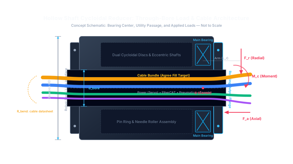
Concept diagram, not a production cross-section or dimensional drawing. Cable fill is illustrative. The bearing type and sleeve arrangement must be confirmed for the selected model.
Main Bearing Architecture: Crossed-Roller vs Dual Angular Contact
A crossed-roller arrangement and a spaced angular-contact pair have different stiffness, preload, speed, and installation requirements. Identify the actual bearing arrangement and request its combined-load calculation, moment-deflection curve, preload conditions, and housing/bolt requirements. A larger bore alone establishes neither higher moment stiffness nor adequate bearing life.
Bearing Dynamic Rating Life under Combined Tilting Moment
ISO 281:2007 provides a rolling-bearing fatigue-life framework with basic rating life at 90% reliability. It does not certify a complete reducer or account for every wear mechanism. For a conventional roller-bearing calculation at constant equivalent load and speed:
L_10h = (C / P)^(10/3) × 1,000,000 / (60 × n)C and P must use the same load units; n is bearing rotational speed in rpm. The exponent is 3 for ball bearings. Use the manufacturer's method to obtain equivalent load P under radial, axial, and moment loading; there is no universal moment-to-load equation suitable for every integrated bearing.
Variable duty, small-angle oscillation, preload, lubrication, contamination, and housing deformation require model-specific evaluation. Do not substitute a simple average speed and peak moment into this equation and report a validated service life. Request both static/peak load checks and a duty-spectrum life calculation.
Worked Engineering Example: Robotic Tool Changer Moment Check
Illustrative inputs only: assume a collaborative robot arm carries a pneumatic gripping tool with an active payload. This is not a tested installation or a quoted product specification:
- Combined mass (tool + workpiece):
m = 12 kg - Radial force due to gravity:
F_r = 12 kg × 9.81 m/s^2 ≈ 117.7 N - Center of mass overhang distance:
L_r = 320 mm = 0.32 m - Axial pressing force during insertion:
F_a = 250 Nat an offsetL_a = 40 mm = 0.04 m - Assumed screening multiplier:
k_d = 2.5. Actual stop loads must come from the motion/inertia model; this factor is not a measured emergency-stop result.
Calculate the illustrative peak moment:
Static Moment M_static = (117.7 N × 0.32 m) + (250 N × 0.04 m)
M_static = 37.66 N·m + 10.00 N·m = 47.66 N·m

Illustrative Peak Moment (assumed multiplier, not a stop-load simulation):
M_peak = M_static × k_d = 47.66 N·m × 2.5 = 119.15 N·m
Compare against hypothetical candidate ratings, solely to demonstrate the arithmetic:
- Candidate A: usable bore 35 mm; assumed permissible peak moment 180 N·m; assumed local moment rigidity
K_M = 120 N·m/arcmin. Neither rating is inferred from the bore diameter.- Angular deflection:
θ = 119.15 / 120 ≈ 0.99 arc-minute. - At a 320 mm tool-tip offset, deflection =
0.32 m × (0.99 × π / 10,800) ≈ 0.092 mm.
- Angular deflection:
- The illustrative moment margin is
180 / 119.15 ≈ 1.51. The 0.092 mm bearing-only deflection has no pass/fail meaning until compared with the application’s tool-tip error budget. It excludes arm, flange, bolt, torsional, and thermal compliance. Confirm the candidate’s combined-load and duty limits; the margin alone does not establish life or precision.
4. Engineering Comparison Matrix: Hollow Transmission Architectures
Compare candidate models at the same load spectrum, envelope, and acceptance conditions. Architecture labels alone do not establish torque density, shock tolerance, lifespan, or total ownership cost. Use this evidence matrix when comparing hollow cycloidal, strain-wave, or planetary proposals:
| Procurement question | Why it changes the decision | Evidence required from each candidate |
|---|---|---|
| Is the complete passage clear? | Adapters, sleeves, and input stages can reduce usable ID | Section drawing and minimum clear diameter through the assembled joint |
| Can the bearing carry the combined loads? | Torque capacity does not establish permissible tilting moment | Combined radial/axial/moment limits with reference center and duty conditions |
| Will tool-tip deflection fit the budget? | Torsional stiffness and tilting stiffness describe different deformation | Both stiffness curves, test load range, mounting, and preload conditions |
| What overloads are permitted? | Repeated acceleration and emergency events have different limits | Rated, acceleration, and momentary torque limits with duration/event count |
| How is lost motion measured? | A single backlash number can conceal different test conditions | Reversal torque, input locking method, temperature, and hysteresis curve |
| Is the claimed life applicable? | Bearing fatigue, flexing elements, seals, and gear wear differ | Duty-based life method, lubrication interval, and applicable failure modes |
| What is the thermal operating limit? | Harness and gearbox losses share the enclosure | Temperature limits and a test plan using the installed harness |
| What does the quotation include? | A lower unit price may exclude integration and maintenance items | Motor adapter, bearing, seals, CAD, validation, spares, and lead-time scope |
If the bore area passes but the moment or tool-tip budget fails, review bearing size, external support, and payload overhang before requesting a larger bore. If the moment check passes but connectors cannot be installed, change the harness assembly plan or aperture. These are separate procurement gates.
For candidate-specific interfaces, compare the hollow shaft product family and request an application review with the unresolved gates marked.
5. Thermal Management & Internal Harness Joule Heating
A compact hollow robot joint can place power, brake, and signal conductors inside an enclosed passage. The installed sleeve and surrounding housing determine how conductor heat escapes. Assess the actual enclosure rather than assuming open-air cable ratings apply.
Electrical Heat Generation (I^2 R)
When high-payload robots perform repetitive acceleration cycles, root-mean-square (RMS) currents generate resistive heating along the conductors:
P_loss = Σ ( I_rms^2 × R_conductor × L_bore )Here R_conductor is resistance per unit length at operating temperature, and the sum covers each current-carrying conductor. Include the return path for DC circuits and use the appropriate phase currents for servo conductors.
Conduction, convection at the exits, sleeve contact, and gearbox losses all affect the resulting temperature. Current alone cannot establish a +15°C or +25°C temperature rise. Measure the hottest accessible harness, sleeve, housing, and seal locations through the intended duty cycle, with ambient conditions and stabilization criteria recorded.
Select cable derating, lubricant, and seal material from those temperatures and supplier compatibility data. NBR and FKM operating limits depend on compound, lubricant, speed, and sealing duty; neither a fixed temperature cutoff nor an automatic FKM upgrade is justified for every assembly.
6. Manufacturing Tolerances & Bore Concentricity Runout
The mechanical integration of a hollow-shaft cycloidal reducer requires control over alignment, runout, and surface condition. Prevent unintended cable contact with moving surfaces and check any rotating interface against its supplier's alignment requirements.
Geometric Tolerances for RFQ Specification
Agree inspection datums and acceptance limits with the reducer and rotary-interface suppliers. The following are example RFQ targets, not universal requirements or a statement of Microcycloidal production capability:
- Bore runout: An example
TIR ≤ 0.015 mmtarget must identify the datum, axial measurement position, assembly state, and whether the bore rotates relative to the harness or union. - Output face alignment: Set face runout/perpendicularity from the tooling error budget and the mounting drawing. Request an inspection method rather than assuming one tolerance fits all flange diameters.
- Bore finish and edges: An example
Ra ≤ 1.6 μmand entry radiusR ≥ 2.5 mmcan start a supplier discussion, subject to geometry and jacket compatibility. Require burr removal and suitable liners or guides; finish alone cannot prevent chafing.
Confirm clearance under tolerance stack-up and thermal expansion. Inspect an assembled sample and run the actual harness through the full travel before approving a batch.
7. Sourcing and Procurement RFQ Checklist
Before issuing a formal Request for Quotation (RFQ) to precision cycloidal reducer manufacturers, review and document each parameter on this engineering checklist:
- Through-bore clear diameter: Define usable minimum ID, largest connector envelope, and an agreed fill target; 40% electrical-only / 30% with hoses are this guide’s screening assumptions.
- Continuous & peak torque spectrum: Specify nominal continuous output torque, repeated acceleration/braking peaks, and maximum emergency-stop torque (
T_stop). - External load profile: Provide radial force (
F_r), axial force (F_a), and the exact distance (L_r, L_a) from the manufacturer-defined bearing center to the load application points. - Tilting moment verification: Confirm combined-load capacity, duty life, and tool-tip deflection. A moment margin of 1.5 is an illustrative screening target, not a universal safety factor; agree the required margin with the supplier and system designer.
- Backlash & lost motion class: Specify allowable lost motion (e.g.,
≤ 1.0 arc-minuteat± 3%of rated torque) and required torsional rigidity (K_TinN·m/arcmin). - Input drive interface: Clarify whether the reducer requires a center-thru multi-crank layout (motor mounted via spur/belt) or an integrated hollow-shaft motor adapter.
- Through-bore surface condition: Agree deburring, liners, finish, and entry/exit radii using the actual cable jacket and installation constraints.
- Internal thermal conditions: State the estimated electrical power dissipation (
I^2 R) inside the bore and ambient operating temperature (e.g.,-10°Cto+45°C). - Sealing & lubrication: Agree required ingress protection and its test conditions, seal/lubricant compatibility, and maintenance intervals. NSF H1 lubricant status alone does not establish medical-device suitability.
- Quality inspection documentation: Request factory inspection records for bore runout, backlash hysteresis curves, and bearing preload torque prior to batch dispatch.
8. Frequently Asked Questions (FAQ)
What is the maximum recommended cable fill factor for a hollow-shaft reducer?
There is no universal limit established by the sources used here. This guide assumes 40% for electrical-only bundles and 30% with hoses to screen available passage area. Use stricter supplier requirements where applicable and validate connectors, separators, bending, torsion, and cycle life in the actual assembly.
How does increasing through-bore size affect cycloidal reducer torque density?
A larger passage competes with internal gearing, bearing, and housing space. It can change the outside diameter, mass, torque rating, or stiffness, but there is no fixed percentage penalty or guaranteed stiffness improvement. Compare dimensioned models at the same load spectrum and ratio.
Can a hollow-shaft cycloidal reducer support continuous 360° rotation?
The mechanical reducer may permit it, but cables clamped at both ends cannot twist indefinitely. Continuous rotation requires suitable rotary electrical/fluid interfaces or another routing arrangement. For finite oscillation, use each cable’s qualified torsion limit and the actual free length; the ±180°/m example above is not a default rating.
Do cycloidal reducers always handle shock loads better than strain-wave gears?
No architecture label establishes an acceptable collision or emergency-stop load. Compare model-specific momentary torque, duration, permissible event count, and bearing limits. A catalogue torque overload percentage is not a permissible tilting moment or proof that the joint will retain its calibrated position after a collision.
How should the internal bore be sealed against oil leaks or factory contaminants?
Confirm whether the selected assembly uses a sealed sleeve to separate the lubricated chamber from the utility passage. Agree the actual sleeve finish, seal compound, shaft speed, lubricant compatibility, and ingress tests with the supplier. A housing IP designation alone does not establish protection at every moving interface.
What is the difference between tilting moment rigidity (K_M) and torsional rigidity (K_T)?
Torsional rigidity (K_T) represents the reducer's resistance to angular deflection about its central rotational axis under applied output torque (N·m/arcmin). Tilting moment rigidity (K_M), on the other hand, measures the resistance of the integrated main bearing to angular tilt or bending deflection when subjected to cantilevered overhung loads or side forces perpendicular to the rotational axis. In robotic wrists and indexing tables, high tilting moment rigidity (K_M) is vital to prevent Tool Center Point (TCP) droop under varying payload weights.
9. References and Verifiable Sources
- ISO 281:2007 — Rolling bearings: Dynamic load ratings and rating life. The public abstract establishes the scope of basic and modified bearing rating life and the 90% reliability basis. It does not validate this article’s example joint, define its cable fill limits, or certify reducer service life.
- Nabtesco Precision Europe — Cycloidal gear portfolio. The official index identifies hollow-shaft RV-C and RD-C families. Portfolio-level benefits must not be treated as ratings for every frame or another manufacturer’s products.
- Nabtesco Precision Europe — RV-C hollow-shaft component family. Product entry linked by the official portfolio as a hollow-shaft component set for robotics; request the selected frame’s current drawings and application limits.
Source review: 29 October 2026. The ISO public abstract and Nabtesco portfolio were inspected; the RV-C entry was identified from the portfolio’s official link. This is not a review of a complete paid standard or a model-specific engineering manual. The fill calculations, decision matrix, and hypothetical load example are this guide’s screening method, not manufacturer test data.
Engineering Consultation and OEM Sample Sourcing
Are you developing a new robot joint, compact wrist assembly, or rotary indexing stage that requires internal through-bore routing?
Prepare your cable harness outer diameters, peak acceleration torques, payload overhang distances, and envelope dimensions. Contact the Microcycloidal engineering team for a through-bore sizing review and OEM sample quotation. Ask the team to confirm candidate-specific bearing checks, usable bore dimensions, drawing/STEP availability, and the sample validation scope before committing to the joint layout.
Explore related products and robotic joint solutions:
Author

Categories
I^2 R)6. Manufacturing Tolerances & Bore Concentricity RunoutGeometric Tolerances for RFQ Specification7. Sourcing and Procurement RFQ Checklist8. Frequently Asked Questions (FAQ)What is the maximum recommended cable fill factor for a hollow-shaft reducer?How does increasing through-bore size affect cycloidal reducer torque density?Can a hollow-shaft cycloidal reducer support continuous 360° rotation?Do cycloidal reducers always handle shock loads better than strain-wave gears?How should the internal bore be sealed against oil leaks or factory contaminants?What is the difference between tilting moment rigidity (K_M) and torsional rigidity (K_T)?9. References and Verifiable SourcesEngineering Consultation and OEM Sample SourcingMore Posts
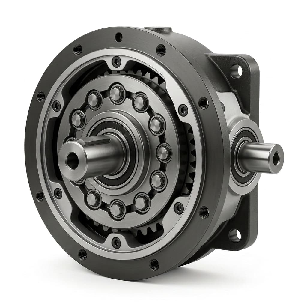
Cycloidal vs Harmonic Drive for Robot Joints: Shock Overload, Torsional Wind-up, and Fatigue Life Tradeoffs
Cycloidal vs harmonic drive for robot joints: compare shock limits, torsional wind-up and fatigue life. Use the checklist to prepare your reducer RFQ.
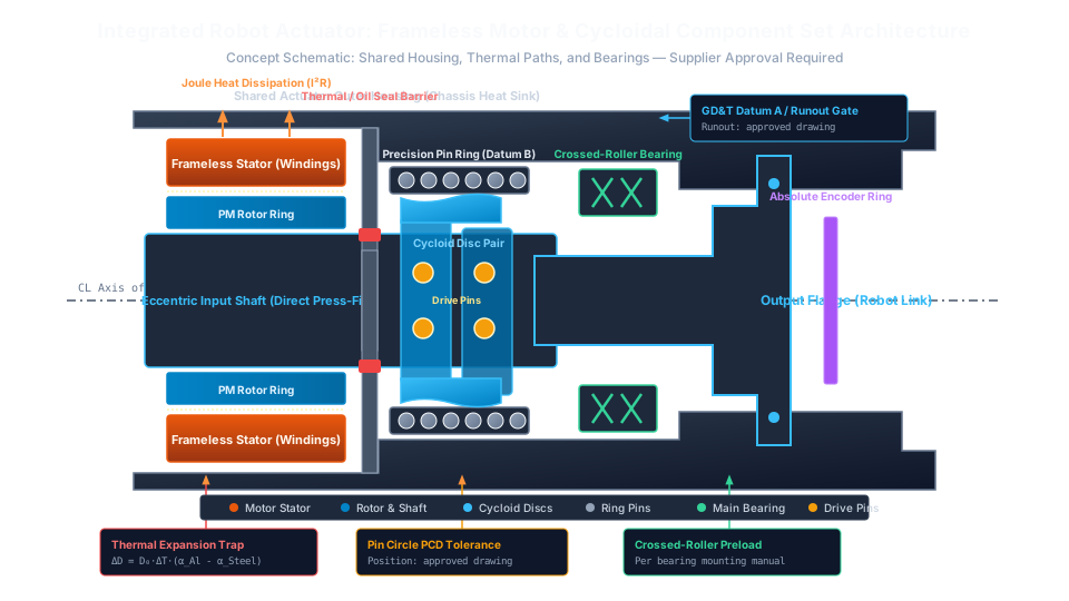
Cycloidal Drive Component Sets for Robot Actuators: Sizing, Tolerance Stack-Up, Thermal Dissipation, and Assembly RFQ Gates
Size cycloidal drive component sets for robot actuators, compare tolerance and thermal risks, and prepare an RFQ with agreed assembly and inspection gates.
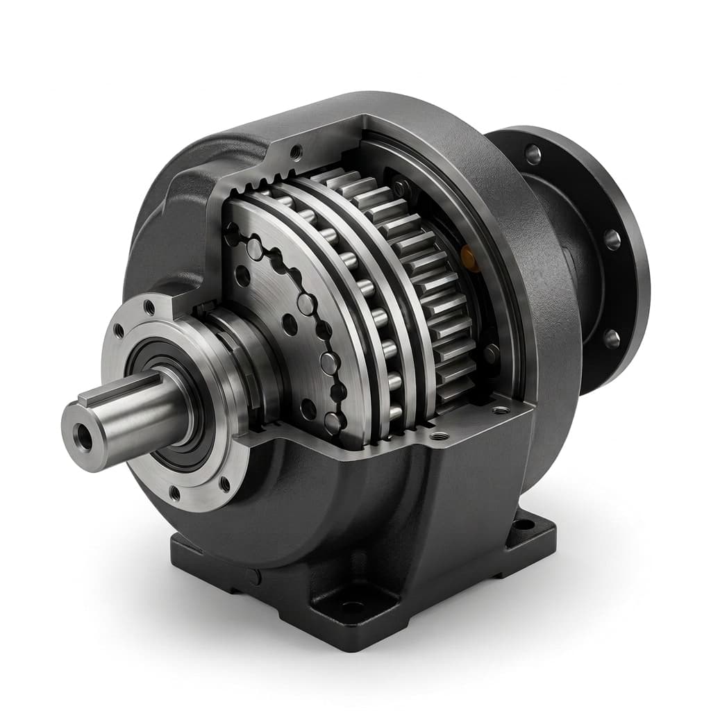
Cycloidal vs Planetary Gearboxes: Tradeoffs for Compact Robotics
An engineering comparison between cycloidal reducers and planetary gearboxes, covering backlash, torsional stiffness, load path, package size, and shock-load review.