
Cycloidal Drive Component Sets for Robot Actuators: Sizing, Tolerance Stack-Up, Thermal Dissipation, and Assembly RFQ Gates
Size cycloidal drive component sets for robot actuators, compare tolerance and thermal risks, and prepare an RFQ with agreed assembly and inspection gates.
Published and reviewed: 2 November 2026. Scope: Global OEM engineering and procurement guide for integrating precision cycloidal drive component sets (cycloid disc pairs, eccentric shafts, needle bearings, pin rings, and output drive pins) into custom robotic joint actuators, collaborative robot arms, dynamic humanoid limbs, and compact indexing mechanisms.
Evidence and modeling boundary: This is a design-review framework, not a report of measured actuator performance. Numerical tolerances and material coefficients below are illustrative inputs, not supplier-approved limits or standard-mandated values. Confirm the component-set drawing, bearing model, thermal path, and test procedure before releasing a custom housing. Stack-up analysis, a thermal model appropriate to the assembly, and prototype testing must cover the intended duty cycle; no safety certification or joint-life guarantee is implied.
Key Takeaways for Sourcing & Actuator Design Leads
Transitioning from off-the-shelf housed gearboxes to bare cycloidal drive component sets (frameless gear kits) can shorten the joint by sharing structural interfaces and removing an external coupling. Quantify the envelope and mass change in a like-for-like CAD assembly including bearings, brake, encoder, seals, and cooling. Moving the gearbox housing into your structural robot link also shifts critical manufacturing and metrology responsibilities to your team:
- Housing geometric dimensioning & tolerancing (GD&T): Establish bearing-seat and pin-ring datums with the supplier. Specify runout, pin position, and inspection conditions on the approved drawing; a housing bore is not automatically a bearing raceway.
- Stator thermal dissipation traps: Motor copper losses share the joint casing with the pin ring. The illustrative 110 mm, 55 K example in Section 4 gives 70.8 µm differential diameter growth, or 35.4 µm radial growth under equal-temperature, unconstrained expansion assumptions. It does not predict angular lost motion.
- Bearing preloading and retention: Use the selected bearing manufacturer's clearance class, housing fits, and mounting procedure. Verify assembled starting torque and hot running clearance instead of applying one preload value to every bearing.
- Contractual warranty and quality demarcation: Backlash, lost motion, and transmission error cannot be guaranteed in the final joint if the customer's housing machining varies. Contractually agree on a factory master-fixture acceptance gate at the supplier's plant before dispatch, alongside incoming quality control (IQC) pin-inspection protocols.
Evaluating a new integrated robot joint, humanoid limb actuator, or compact rotary gimbal? Review the RFQ procurement gates in Section 7 and request an engineering component-set integration review with your joint envelope STEP file and motor torque-speed curve.
1. Mechanical Operating Principles: Housed Gearhead vs Bare Component Set
In a conventional robotics powertrain, an electric motor with its own housing and front flange is coupled via an elastomeric spider or metallic bellows coupling to an enclosed, pre-lubricated cycloidal reducer. While simple to procure and replace, this architecture introduces substantial engineering compromises:
Conventional Housed Powertrain:
Motor Housing -> Motor Bearings -> Shaft -> Coupling -> Reducer Input Shaft -> Eccentric Bearings -> Cycloid Discs -> Pin Ring -> Main Bearing -> Output Flange
[Result: Long axial length, multiple stacked runout interfaces, torsional wind-up in coupling]

Integrated Component Set Actuator:
Joint Housing (Motor Stator + Pin Ring) -> Frameless Rotor on Eccentric Shaft -> Dual Cycloid Discs -> Precision Ring Pins -> Output Crossed-Roller -> Direct Output Link
[Result: Potentially shorter axial footprint, no external coupling, shared thermal path]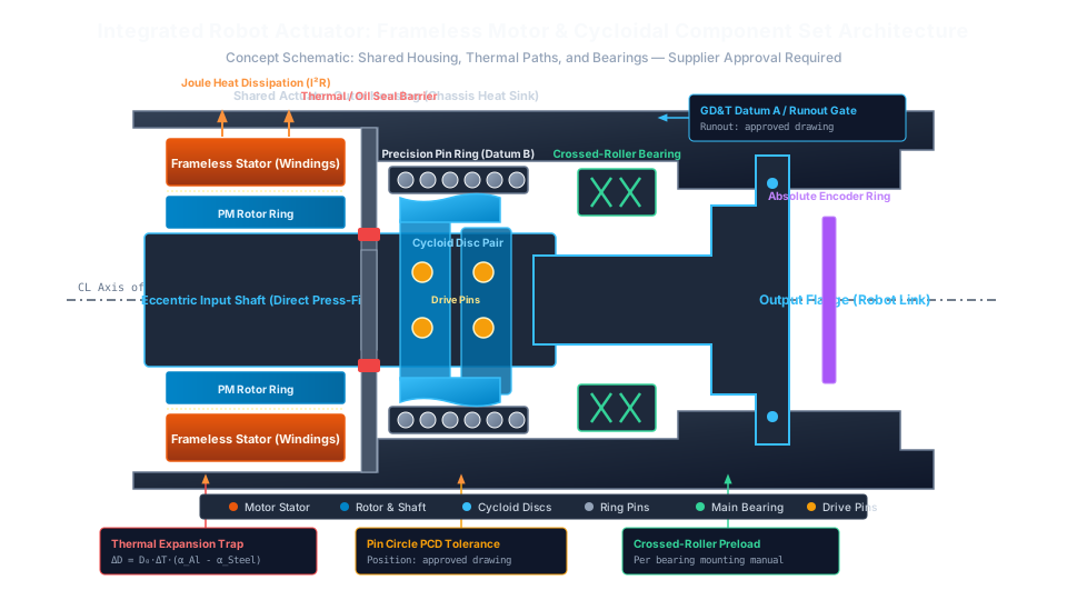
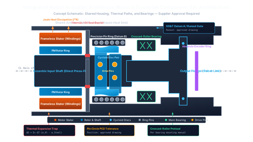
Concept schematic, not an assembly drawing or measured test result: shared housing, motor heat path, eccentric shaft, disc pair, output bearing, and inspection interfaces. Fits, load paths, and thermal barriers require model-specific approval.
When selecting a cycloidal drive component set, the gear mechanism is broken down into its fundamental kinetic elements:
- Eccentric input shaft & needle roller bearings: High-speed input shaft with dual eccentric lobes ground
180°apart, balancing primary dynamic centrifugal forces. - Cycloidal disc pair: Matched, precision-ground discs with modified cycloidal profiles. Confirm the steel grade, heat treatment, and profile revision for the selected set rather than assuming all bearing and carburizing steels are interchangeable.
- Pin wheel ring & precision pins: A circular array of hardened needle rollers or cylindrical pins anchored into the outer housing pitch circle, acting as the reaction stator.
- Output drive pins & carrier flange: Cylindrical pins fitted with low-friction rotating bushes that protrude through oversized counter-bores in the cycloid discs to extract pure reduced planetary rotation.
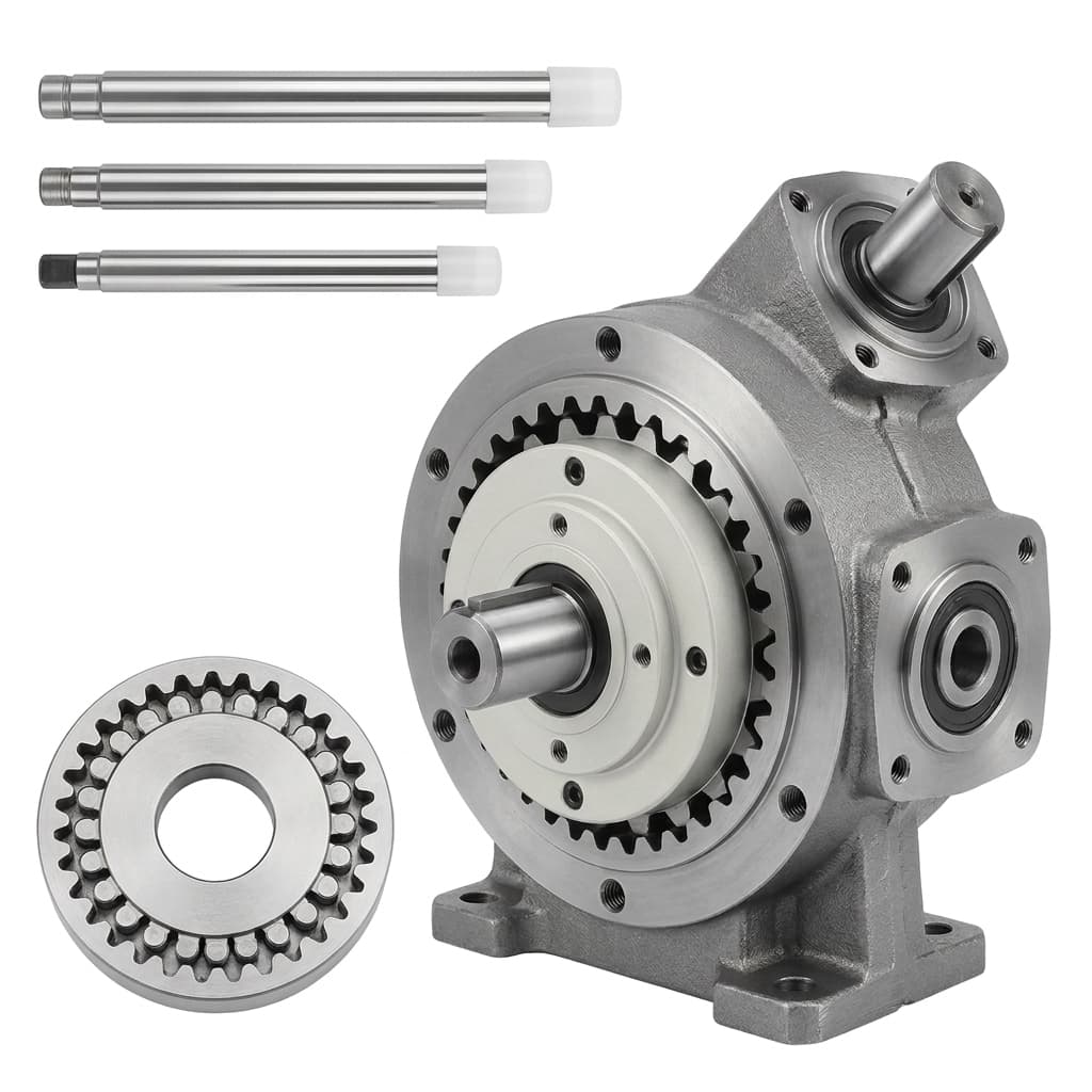
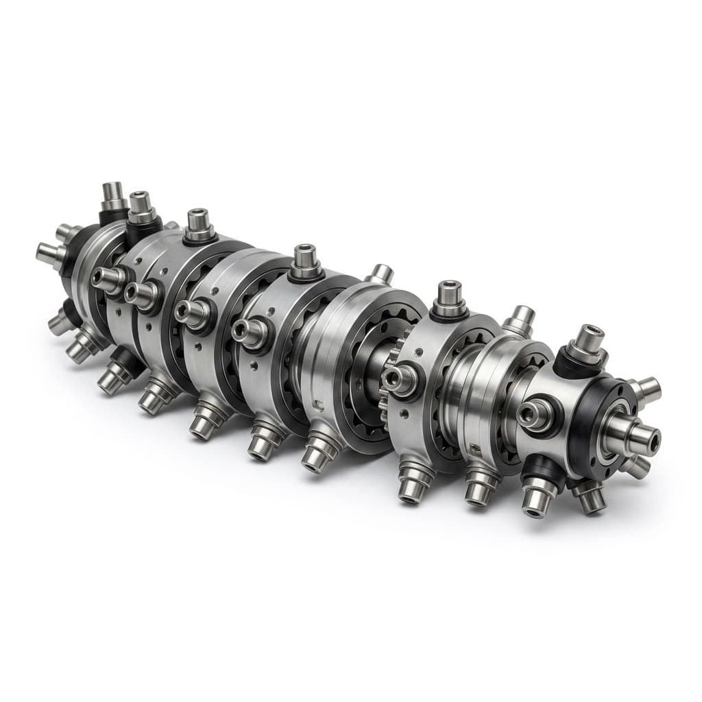
Illustrative product image from the site catalogue. It is not inspection evidence for a particular component set; obtain the actual shaft drawing and dimensional report with the RFQ.
2. Component Set vs Enclosed Gearhead: Sourcing & Architecture Matrix
Deciding whether an actuator development program should purchase fully enclosed, housed cycloidal gearheads (such as standard servo-flange units) or bare component kits is a multi-disciplinary decision spanning mechanical envelope, thermal budgets, assembly tooling, and vendor accountability.
The following comparison matrix evaluates these two approaches across 8 core engineering and procurement dimensions:
| Sourcing & Engineering Metric | Enclosed Housed Gearbox | Bare Cycloidal Component Set | Impact on Sourcing & Joint Design |
|---|---|---|---|
| Axial Joint Envelope | Separate motor case, adapter, coupling, and reducer enclosure occupy axial space. | Shared interfaces can remove some stack length; brake, encoder, and bearing depth still count. | Compare complete CAD envelopes at the same load, ratio, and cooling duty. |
| Total Actuator Mass | Includes motor end-bells, reducer flanges, fasteners, and coupling hubs. | Can share a chassis; added support, liners, and cooling may offset savings. | Weigh the complete bill of materials before claiming torque-density gains. |
| Torsional Compliance & Bandwidth | Coupling compliance acts in series with reducer and structure compliance. | Removes the external coupling; rotor attachment, bearings, and housing still deflect. | Measure assembled stiffness and resonances before changing control-loop gains. |
| Thermal Dissipation Dynamics | Separate enclosures provide distinct heat paths, with conduction across their mounting interface. | Motor and gear losses heat a shared housing. | Model gradients and verify hot clearance, grease temperature, and motor cooling. |
| Machining Accuracy Responsibility | Supplier controls internal datums to the contracted drawing. | Customer controls housing datums and assembly distortion. | Qualify the machining and metrology process against agreed tolerances; machine axis count alone is insufficient. |
| Lubrication & Contamination Sealing | Fill, seal arrangement, maintenance interval, and IP rating are model-specific. | Customer must define grease retention and motor/encoder separation. | Confirm lubricant, elastomer, winding, and adhesive compatibility. |
| Assembly Equipment & Labor | Usually fewer internal assembly steps; follow the mounting manual. | Requires controlled cleanliness, fit tooling, calibrated torque tools, and dimensional checks. | Validate work instructions and assembly yield during pilot production. |
| Quality & Warranty Demarcation | Acceptance and remedies follow the purchase agreement. | Separate component/master-fixture acceptance from in-housing acceptance. | Agree measurement conditions, responsible parties, and remedies before ordering. |
First-Pass Ratio and Torque Sizing
Start with the output torque-speed-time trace, including payload, gravity, acceleration, external forces, and stopping events. For reduction ratio N = n_input / n_output, check n_input = N × n_output at every operating point. A motoring estimate is T_motor ≈ T_output / (N × η); efficiency η must come from the selected reducer at the relevant speed, load, lubricant, and temperature. Backdriving requires a separate efficiency model.
For a segmented duty cycle, calculate T_RMS = sqrt(Σ(T_i² × t_i) / Σt_i) as an initial thermal screening value. Confirm the supplier's actual rating method; RMS torque alone cannot establish gear fatigue life or allowable peak duration. Approve continuous duty, repeated peaks, emergency loads, bearing moments, and thermal limits separately. Hold the RFQ for engineering review if the load trace, peak duration, or candidate rating is unknown.
3. Geometric Dimensioning & Tolerances (GD&T): Housing Stack-Up Formulation
Housing distortion, bearing fits, pin position, disc profile modification, and elastic deformation all affect cycloidal mesh clearance and load sharing. Micrometre-scale errors can matter, but their effect depends on the actual geometry and load. No universal pin-engagement percentage or contact-stress multiplier is established by the sources below.
Load-Sharing Review:
Approved profile + controlled pin positions -> intended multi-pin contact
Housing or pin-position error -> uneven load sharing and possible edge loading
Required evidence -> model-specific contact analysis and inspection under load
Critical Machining Tolerances for Custom Actuator Housings
The following values are illustrative drawing-review targets, not universal release limits. Establish Datum A as the agreed bearing-seat axis and define the other datum features on the drawing. Obtain supplier approval for each tolerance, inspection temperature, and method; this table does not establish an angular backlash or bearing-life rating.
| Housing & Shaft Feature | Geometric Characteristic | Illustrative Review Target (mm) | Risk to Evaluate |
|---|---|---|---|
| Pin Ring Pitch Circle (PCD) | True Position (⌀) | ≤ 0.008 mm (to Datum A) | Uneven pin engagement, cyclical torque ripple, accelerated disc lobe wear. |
| Pin Housing Bore Roundness | Circularity / Cylindricity | ≤ 0.005 mm | Pin ring ovality, periodic binding, alternating backlash around 360° rotation. |
| Main Bearing Outer Seat | Total Indicated Runout (TIR) | ≤ 0.010 mm (to Datum A) | Overturning angular deflection, tool center point (TCP) wobble under load. |
| Eccentric Bearing Pilot Journal | Cylindrical Runout | ≤ 0.004 mm | High-frequency input shaft vibration, reduced L_10h eccentric bearing life. |
| Motor Stator Bore to Pin Ring | Total radial runout to Datum A | ≤ 0.012 mm | Unbalanced magnetic pull (UMP) on motor rotor, parasitic radial load on shaft. |
| Output Pin Carrier Pitch Circle | True Position (⌀) | ≤ 0.008 mm | Lost motion increase, uneven shear loading on carrier drive pins. |
| Housing Mating Flange Face | Perpendicularity | ≤ 0.006 mm (per 100 mm) | Bearing race cocking, uneven preload, increased breakaway starting torque. |
Worked Mathematical Formulation: Scalar Radial Error Stack-Up
Consider a custom robotic elbow joint where the frameless motor stator and cycloidal pin ring share a common machined aluminum shell (Datum A), and the output carrier is supported by an integrated crossed-roller bearing:
For an illustrative scalar stack, express all contributions as radial offsets along the same sensitivity direction. Assume independent, zero-mean errors whose quoted values represent the same statistical coverage. RSS then estimates combined statistical spread; it is not vector addition or a worst-case acceptance limit. Drawing TIR and diametral position zones must first be converted to compatible radial contributions using the actual geometry.
δ_total = sqrt(δ_stator-bore² + δ_bearing-runout² + δ_shaft-eccentricity² + δ_pin-PCD²)Assumed equivalent radial contributions, independent of the drawing-review table:
- Motor pilot alignment contribution:
δ_stator-bore = 0.008 mm - Main bearing alignment contribution:
δ_bearing-runout = 0.006 mm - Eccentric journal alignment contribution:
δ_shaft-eccentricity = 0.004 mm - Pin-circle location contribution:
δ_pin-PCD = 0.006 mm
Calculating the combined statistical radial error:
δ_total = sqrt(0.008² + 0.006² + 0.004² + 0.006²) mm
        = sqrt(0.000152) mm
δ_total ≈ 0.0123 mm = 12.3 µmEngineering Decision Gate: RSS gives 12.3 µm. If the same magnitudes were hard bounds, their worst-case scalar sum would be 24.0 µm. Compare the appropriate result with the supplier-approved mesh and alignment budget; neither result predicts jamming or angular lost motion by itself. Correlated errors, press-fit distortion, and thermal shifts need separate treatment.
Machining related bores in one setup can reduce re-clamping error. Qualify the resulting parts by inspection rather than treating a particular machine type or setup as proof of compliance.
4. Thermal Trapping & Differential Expansion Modeling
Both architectures dissipate gear, bearing, and seal losses, and can receive heat from adjacent equipment. In an integrated joint, the frameless motor adds a nearby heat source to the shared housing.
During heavy robotic manipulation or continuous collaborative welding cycles, the stator generates continuous Joule heating (I²R copper losses) plus iron core eddy losses:
P_motor-loss = 3 × I_rms² × R_phase + P_ironHere I_rms is RMS phase current and R_phase is per-phase resistance at the relevant winding temperature for balanced three-phase operation. Add motor, reducer, bearing, and seal losses to the assembly heat budget. Winding temperature is not pin-ring temperature: use a thermal network or simulation, then measure both under the stated cooling and duty conditions.
Thermal Expansion Coefficient Mismatch:
Approximate screening inputs, to be replaced with material-specific data:
Aluminum: α_Al ≈ 23 × 10^-6 / K
Steel:    α_Steel ≈ 12 × 10^-6 / K
Differential Radial Growth Formulation
For unconstrained, uniform expansion of an aluminum bore and a steel reference diameter, both initially D₀ and both experiencing the same temperature rise ΔT, the screening model is:
ΔD = D₀ × ΔT × (α_Al − α_Steel)ΔC_r = ΔD / 2 = D₀ × ΔT × (α_Al − α_Steel) / 2Worked Hypothetical Example: Humanoid Knee Joint at Elevated Temperature
Assume a nominal reference diameter D_0 = 110 mm for an aluminum housing and steel ring. The values below are example inputs, not measured temperatures or certified alloy data:
- Ambient room temperature:
T_0 = 20°C - Continuous duty operating temperature under load:
T_op = 75°C(ΔT = 55 K) - Housing material: Aluminum 7075-T6 (
α_Al = 23.4 × 10⁻⁶/K) - Cycloid disc and pin material: Hardened GCr15 steel (
α_Steel = 11.7 × 10⁻⁶/K)
Calculate the diametral growth differential:
ΔD = 110 mm × 55 K × (23.4 − 11.7) × 10⁻⁶ / KΔD = 6050 × 11.7 × 10⁻⁶ mm ≈ 0.0708 mm = 70.8 µmΔC_r = 70.8 µm / 2 = 35.4 µmScreening Result:
- Differential diameter growth: 70.8 µm
- Differential radial growth: 35.4 µm
- Angular lost motion: not determined by this calculationMitigation Strategies for Actuator Designers
A constrained press fit, separate pin-ring structure, and unequal temperatures change this result. For unequal temperatures use ΔD = D₀ × (α_Al × ΔT_Al − α_Steel × ΔT_Steel). Actual backlash requires the tooth/pin geometry, fits, loading, and hot test data. Evaluate these mitigation options:
- Steel pin-ring carrier or liner: Assess fit retention, contact pressure, roundness, and heat transfer across the full temperature range; similar expansion coefficients alone do not eliminate housing distortion.
- Separated thermal paths: Preserve an effective stator-to-ambient cooling path while limiting unwanted gear heating. A barrier that traps motor heat can worsen winding temperature; review stiffness, creep, sealing, and temperature limits of any isolator.
- Supplier-designed profile compensation: Request a validated cold/hot clearance design. Do not specify negative gear clearance independently: cold-start binding, input torque, and hot lost motion all require prototype acceptance tests.
If the hot-clearance budget remains unresolved, request a housing and thermal-path DFM review with your assumed component temperatures and fit drawings before releasing tooling.
5. Bearing Preload, Lubrication & Contamination Isolation
A cycloidal component set does not include its own structural enclosure. The actuator designer must engineer the internal bearing support and dynamic sealing barriers.
Output Crossed-Roller Bearing Sizing & Preload
An output crossed-roller bearing can carry radial, axial, and moment loads in one bearing, as described in THK's official cross-roller overview. Use the selected bearing's load-combination equations and mounting manual; there is no universal equivalent-load formula or clearance class covering every crossed-roller design.
ISO 281:2007 provides a rolling-bearing dynamic-rating and fatigue-life framework. It does not prescribe the preload for this actuator. Its scope also limits application to rollers running directly on a shaft or housing unless that surface is equivalent to the raceway it replaces. Check static capacity, oscillatory motion, lubrication, contamination, housing stiffness, and tilt moment separately with the bearing supplier.
Specify the approved clearance/preload class, fits, mounting sequence, fastener torque, and starting-torque acceptance window. Excess preload can increase friction and heat; insufficient support can permit output deflection. Verify both cold assembly and hot duty instead of adopting a generic micrometre preload target.
Lubricant Selection & Migration Barriers
In an integrated actuator, review lubricant migration paths between the gear chamber, motor, and encoder:
- Encoder contamination: Grease or oil mist can obscure optical codewheels. Check the encoder manufacturer's contamination and sealing requirements; magnetic and optical encoders have different sensitivities.
- Motor material compatibility: Obtain lubricant compatibility confirmation for winding enamel, adhesives, potting, and seals. Base-oil family alone does not establish compatibility or electrical insulation performance.
Lubrication Release Checklist:
- Supplier-approved lubricant, fill quantity, orientation, and replenishment plan
- Viscosity and consistency selected for speed, load, and temperature, not OD alone
- Seal material and lip design verified for lubricant, shaft finish, speed, and heat
- Separate retention barriers for the motor air gap and encoder cavity
6. Factory Master-Fixture Acceptance vs In-Housing Quality Gates
A useful hypothetical acceptance dispute illustrates why test boundaries matter:
The OEM's claim: "We assembled your cycloidal component set into our joint, and the measured lost motion is 2.8 arcmin, whereas your sales drawing promised ≤ 1.0 arcmin. The components are defective."
The Supplier's response: "Our cycloid discs were ground to sub-micron accuracy. Your CNC machine shop machined the pin ring housing bore out-of-round by 15 microns, causing the loose backlash."
To protect both buyer and supplier, an unambiguous contract demarcation must be established in the procurement agreement.
Proposed Quality Demarcation Workflow (agree values in the purchase specification):

Step 1: Supplier Factory Gate
Component Set -> Tested in a calibrated master fixture at an agreed temperature
- Measure lost motion at agreed bidirectional test torques (e.g., ±3% rated torque)
- Record Hysteresis Curve & Torsional Rigidity
- Inspect modified cycloidal profile and pin positions to the approved drawing
- Record fixture ID, part IDs, uncertainty, and criteria -> approve or hold shipment

Step 2: Customer Assembly Gate
Customer machines housing -> IQC CMM inspection to approved datum/fit tolerances
- Housing PASS: Proceed to controlled-cleanliness component-set assembly
- Housing FAIL: Re-machine or scrap housing before installing gear set
- After assembly: repeat lost-motion, starting-torque, and hot-duty checks
Master-fixture acceptance verifies the set under stated fixture conditions. It does not certify the finished actuator or remove contractual responsibility for a defective component. Agree the investigation process for discrepancies between fixture and assembled-joint results.
7. Sourcing and Procurement RFQ Checklist for Component Sets
Before issuing a formal Request for Quotation (RFQ) for custom cycloidal drive component sets, compile the parameters below to ensure rapid engineering feasibility assessment and accurate prototype lead times:
- Reduction ratio & kinematic speed: Specify primary reduction ratio (e.g.,
19:1,29:1,43:1,59:1,89:1), maximum input continuous RPM, and peak emergency overspeed. - Rated & peak output torque: State nominal continuous torque (
T_N), repeated acceleration/deceleration peak torque (T_acc), and maximum emergency-stop torque (T_stop), with duration, frequency, and lifetime cycle count for each load case. - Frameless motor pairing data: Provide motor manufacturer, part number, rotor inner/outer diameter, stator stack length, continuous stall current, and peak phase current.
- Eccentric shaft input interface: Clarify whether the motor rotor is directly press-fitted onto the eccentric shaft, bonded with structural retaining compound, or driven via an internal spline/keyway.
- Housing dimensional boundaries: Specify maximum allowable outer diameter (OD) and axial depth (
L_max) for the pin ring and cycloid discs. - Thermal operating spectrum: Document estimated motor stator continuous temperature rise (
ΔT_stator), ambient environment range (e.g.,-20°Cto+50°C), and housing material alloy (Aluminum 6061-T6, 7075-T6, Magnesium, or Steel). - Backlash & lost motion acceptance: Agree test torque, input locking, loading sequence, temperature, fixture stiffness, uncertainty, and allowable angle. If using ±3% of rated torque, state it explicitly; separate master-fixture and assembled hot-joint limits.
- Surface finish & heat treatment: Request steel grade, heat-treatment route, applicable hardness/case-depth limits, and flank/journal roughness on the approved drawing. Through-hardened and carburized parts need different acceptance criteria.
- Main bearing integration scope: Clarify whether the quotation must include a matched crossed-roller output bearing or if your team will procure the bearing separately.
- Batch inspection documentation: Require master-fixture hysteresis test reports, CMM pin-circle inspection sheets, and material traceability certificates with each production batch.
8. Frequently Asked Questions (FAQ)
When should an engineering team switch from an enclosed gearbox to a component set?
Consider a component set when axial length or mass is a major bottleneck and your team can own housing manufacture, thermal design, assembly, and metrology. If you lack the process capability for the supplier-approved datums and fits, a housed gearbox usually reduces integration work. Confirm the actual envelope benefit in complete actuator CAD.
Can we install a cycloidal component set directly into an unlined aluminum housing?
Only if the selected set's housing design and full temperature range are validated. In the equal-temperature example above, differential diameter growth is 70.8 µm and radial growth is 35.4 µm; neither value determines angular backlash. Compare an unlined design, a steel carrier, and supplier-designed profile compensation using cold/hot fit analysis and prototype measurements.
How is lost motion measured on a bare component set before it is installed into my joint?
Agree a calibrated master fixture with the supplier, lock the input, and record output angle during a specified bidirectional torque cycle. Define the lost-motion reading points, temperature, fixture compliance, run-in, and measurement uncertainty in the purchase specification. A ±3% rated-torque reading point can be proposed, but this guide does not establish it as a verified standard requirement. Repeat acceptance in the final housing; a fixture does not automatically remove housing nonlinearities.
What is the typical assembly tool requirement for installing component sets in-house?
Follow the selected set and bearing mounting instructions. Typical needs include a clean assembly area, calibrated torque tools, fit/press fixtures that avoid transmitting force through rolling elements, and dimensional gauges. Use heating or cooling only within approved material, bearing, and lubricant limits; manage condensation and contamination.
Why do cycloidal component sets use two cycloid discs instead of a single disc?
A matched pair arranged 180° out of phase can balance primary eccentric forces and share load. Residual unbalance, axial separation, profile differences, and assembly error still matter. Confirm the supplied architecture: not every cycloidal reducer uses the same disc and crank arrangement, and two discs do not automatically double allowable torque.
How does torque ripple in a cycloidal component set interact with frameless motor cogging?
Motor cogging, current-control error, friction, and load-dependent gear transmission error can all contribute. Dual encoders and characterized feed-forward compensation may help, but require assembled-joint measurements across load, speed, and temperature. Control compensation cannot approve an out-of-tolerance housing or guarantee smooth motion.
9. References and Verifiable Sources
- ISO 281:2007 — Rolling bearings — Dynamic load ratings and rating life. Official abstract supports the bearing rating-life framework and its raceway applicability limits; it does not specify actuator preload or certify this integration.
- THK — Cross-Roller Ring / Double Row Ring. Official overview supports the combined radial, axial, and moment-load capability discussed in Section 5. Select fits and preload from the actual bearing's documentation.
- Nabtesco Precision Europe — Cycloidal gears. Official portfolio distinguishes component sets and gearbox families. It provides architecture context, not ratings or assembly tolerances for Microcycloidal parts.
Source inspection note: These three public pages were checked on 2 November 2026. Only their public scope and product descriptions are cited; this guide does not claim a full standards-conformance review. The RSS and thermal examples use disclosed assumptions and are reproducible arithmetic, not physical test data. Resolve final acceptance limits through the selected supplier's drawings and signed test plan.
Engineering Consultation and OEM Component Set Sourcing
Are you developing a custom integrated robot joint, humanoid dynamic actuator, or high-torque rotary positioner requiring bare cycloidal component sets?
Prepare your target reduction ratio, motor rotor/stator dimensions, housing envelope STEP files, and torque-speed duty trace. Contact the Microcycloidal engineering team for a component-set integration review and prototype quotation. Request confirmation of the review scope, available master-fixture evidence, and prototype acceptance plan before authorizing tooling.
Explore related precision components and robotic joint solutions:
Author

Categories
More Posts
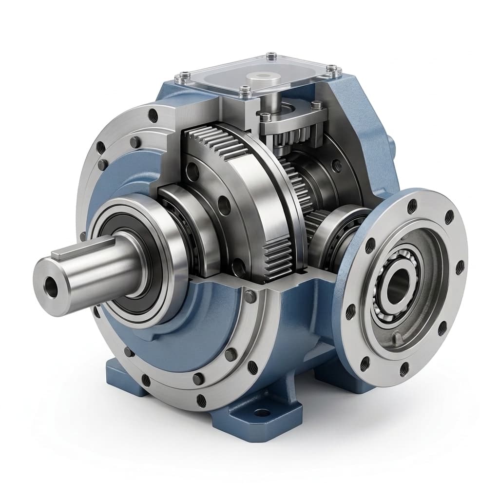
How to Select the Right Cycloidal Reducer for AGV and AMR Drive Wheels
A highly technical sizing guide for OEM engineers selecting cycloidal reducers for Automated Guided Vehicles (AGVs). Includes torque formulas, radial load calculations, and duty cycle analysis.
Cycloidal vs Planetary Gearboxes: Tradeoffs for Compact Robotics
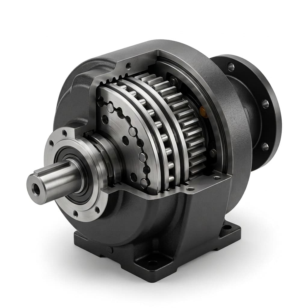
An engineering comparison between cycloidal reducers and planetary gearboxes, covering backlash, torsional stiffness, load path, package size, and shock-load review.
Understanding Low Backlash in Precision Gearboxes: Where Cycloidal Drives Fit
A technical exploration of how low backlash is specified and verified, comparing cycloidal preload with harmonic and planetary gearbox tradeoffs.