
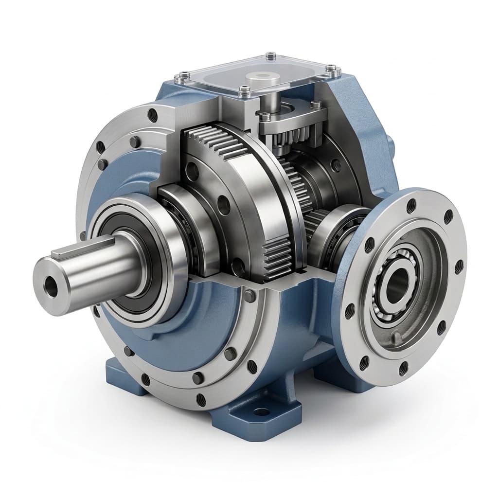
How to Select the Right Cycloidal Reducer for AGV and AMR Drive Wheels
A highly technical sizing guide for OEM engineers selecting cycloidal reducers for Automated Guided Vehicles (AGVs). Includes torque formulas, radial load calculations, and duty cycle analysis.
Key Takeaways for Sourcing Engineers:
- Drive Wheel Demands: Modern AMRs require transmissions that support heavy radial loads directly on the output shaft while delivering zero-speed torque.
- The Solution: Compact cycloidal reducers are replacing planetary drives in heavy AGVs because they integrate ISO 14728 rated crossed-roller bearings directly into the housing.
- Sizing Rule of Thumb: Size your reducer for the peak torque required to overcome static traction friction (slip torque) fully loaded on an incline.
- IP Rating: Specify IP65 or IP67 sealing with Viton (FKM) rotary seals to protect internal kinematics from factory floor debris and fluids.
Modern free-roaming AMRs require drive wheel modules that can handle massive vertical payloads, deliver high torque at near-zero speeds, and eliminate positioning drift—all while fitting into increasingly dense chassis designs.
Because of these constraints, the compact cycloidal reducer is becoming the standard baseline for heavy-duty AGV/AMR drive wheels.
If you are sizing a new AMR drive module, use this guide to calculate torque requirements, evaluate radial loads, and draft your RFQ specs.
1. Calculating Required Drive Torque
You cannot rely on motor wattage alone; you must calculate the specific torque required at the wheel. The required torque consists of continuous running torque and peak (acceleration/incline) torque.
The Physics Formula
To calculate the continuous running torque (Tc) required for a flat surface:
Tc = (m x g x mu x r) / (eta x i)
Where:
- m = Total mass (AGV chassis + max payload) in kg
- g = Acceleration due to gravity (
9.81 m/s^2) - mu = Coefficient of rolling friction (typically 0.03 to 0.05 for polyurethane wheels on concrete)
- r = Radius of the drive wheel in meters
- eta = Mechanical efficiency of the cycloidal reducer (typically 0.85)
- i = Reduction ratio
Peak Torque for Inclines
If your AGV must traverse ramps, you must factor in the incline angle (theta):
Tpeak = (m x g x (mu x cos(theta) + sin(theta)) x r) / (eta x i)
Sizing Rule: Ensure the chosen cycloidal reducer's Rated Torque is >= Tc, and its Maximum Acceleration Torque is >= Tpeak. Cycloidal reducers excel here because their compression-based rolling elements can handle peak torques up to 5 times their nominal rating without damage.
2. Radial Load Capacity and Integrated Bearings
In a direct-drive hub configuration—where the wheel is bolted directly to the gearbox output flange—the gearbox must act as the primary structural support.
The payload of a 2-ton AGV rests directly on the reducer's internal bearings. Traditional planetary gearboxes require the OEM to design secondary external bearing blocks to prevent the output shaft from snapping under this radial load.
The Cycloidal Solution: High-grade cycloidal reducers designed for AGVs feature integrated crossed-roller bearings or massive dual angular-contact ball bearings built directly into the housing. These bearings are rated under ISO 14728 (Rolling bearings — Linear motion rolling bearings) to handle complex multi-directional loads.
AGV Drive Hub Architecture: Planetary vs Cycloidal
The chassis needs extra bearing structure to protect the gearbox output shaft.
The reducer package absorbs multi-directional loads without a secondary support block.
When selecting a reducer, check the manufacturer's Permissible Radial Load and Permissible Bending Moment specs. In some layouts, an integrated support-bearing arrangement can reduce or simplify external bearing structures, but the load path and wheel offset should be confirmed before removing secondary supports.
3. Backlash and SLAM Navigation Drift
Modern AMRs navigate using Lidar and SLAM (Simultaneous Localization and Mapping). The navigation controller calculates position based on wheel odometry (encoder feedback from the motor).
If the gearbox has "lost motion" (backlash), the motor encoder may register movement while the physical wheel response lags. On long warehouse runs, excessive backlash can contribute to docking or pallet-pick errors, especially when wheel diameter, controller compensation, and floor conditions are not accounted for.
Some precision cycloidal reducer designs can be specified in low-arc-minute backlash ranges, but the accepted target is model-, preload-, and duty-cycle-dependent. Treat backlash as an acceptance item in the RFQ and verify it against the AMR's odometry and docking requirements.
4. Thermal Dissipation and Duty Cycle
Because cycloidal reducers are exceptionally compact, their surface area for heat dissipation is limited. AGV chassis are often tightly sealed against dust and water (IP65+), meaning internal ambient temperatures can rise rapidly.
When speaking with your reducer supplier, define your Duty Cycle clearly:
- Continuous (S1 Duty): Operating 24/7 without stopping (requires specialized low-viscosity grease and potentially a lower reduction ratio to prevent overheating).
- Intermittent (S3/S4 Duty): Moving between picking stations with pauses.
Standard cycloidal drives are packed with high-grade semi-fluid grease. If your internal chassis temperature is expected to exceed 60°C during heavy continuous operation, request high-temperature synthetic grease and verify the thermal expansion coefficients of the internal oil seals.
5. Wheel Traction and Dynamic Slip
When calculating required torque, do not ignore the physical limitation of the wheel material. The maximum usable torque is limited by the traction limits of your wheel.
Tslip_limit = m_drive x g x mu_static x r
Where m_drive is the mass resting over the drive wheels and mu_static is the static friction coefficient.
| AGV Wheel Material | Typical mu_static (on concrete) | Best Application Scenario |
|---|---|---|
| Polyurethane (PU) 90A | 0.6 - 0.7 | Heavy payloads, clean indoor floors |
| Natural Rubber | 0.8 - 0.9 | Slopes, uneven or wet surfaces |
| Nylon / Delrin | 0.3 - 0.4 | Extremely heavy static loads (low friction) |
Traction Tip: If your cycloidal reducer produces more torque than Tslip_limit, the wheel will spin in place during high acceleration, accelerating wear on the PU tread. Ensure the reducer's control loop limits the acceleration torque to just below the slip threshold.
6. Environmental Sealing and IP Ratings
AMRs are increasingly deployed in cold-storage warehouses, damp agricultural environments, and outdoor logistics yards. Standard industrial gearbox sealing may be insufficient for outdoor AMR drive wheels.
For drive wheels exposed to condensation, pressure washing, or puddles, specify a cycloidal reducer with an IP65 or IP67 rating. This requires:
- Dual-lip Fluororubber (FKM/Viton) oil seals on the output flange to prevent water ingress while handling internal pressure build-up.
- Anti-corrosion surface treatments: Standard black oxide may not be suitable for wet or outdoor exposure. Consider Electroless Nickel Plating (ENP) or specialized epoxy marine coatings for the exposed output flange and housing.
Sourcing RFQ Checklist
When requesting a quotation (RFQ) for an AMR cycloidal reducer, incomplete data can lead to incorrect sizing. Provide the supplier with this checklist:
- Total Mass (Max Payload + AGV weight): e.g., 1,500 kg
- Wheel Diameter: e.g., 200 mm
- Max Speed: e.g., 1.5 m/s
- Max Incline: e.g., 5 degrees
- Duty Cycle & Operating Environment: e.g., S3 duty, indoor warehouse, 0-40°C
- Input Interface: Send the dimensional drawing of your input flange, shaft, and bolt pattern.
Micro Cycloidal provides direct factory engineering support for OEM drive wheel applications. Submit your RFQ parameters today for a rapid sizing validation and CAD model.
Author

Categories
More Posts
Understanding Low Backlash in Precision Gearboxes: Where Cycloidal Drives Fit
A technical exploration of how low backlash is specified and verified, comparing cycloidal preload with harmonic and planetary gearbox tradeoffs.
Cycloidal vs Planetary Gearboxes: Tradeoffs for Compact Robotics
An engineering comparison between cycloidal reducers and planetary gearboxes, covering backlash, torsional stiffness, load path, package size, and shock-load review.