
Cycloidal Reducer Lubrication, Thermal Dissipation, and L10h Life: Sizing, Viscous Churning, and Sealed Actuator Sourcing Guide
Review cycloidal reducer lubrication, grease fill, thermal losses, and ISO 281 bearing life. Prepare a duty-cycle RFQ for sealed robotic actuator sourcing.
Published and reviewed: 12 November 2026. Scope: Global OEM engineering and procurement guidance for grease-lubricated, sealed cycloidal reducers in robotic joints and positioning actuators. The audience includes mechanical designers, actuator integration leads, quality engineers, and component buyers. Oil-lubricated industrial reducers, vacuum systems, and regulated medical applications require separate qualification.
Evidence and modeling boundary: This is a design-review methodology, not a report of physical testing. Worked examples use stated, hypothetical inputs; they are neither product ratings nor customer results. Bearing relationships are supported by manufacturer technical literature. Lubricant chemistry, fill quantity, operating temperature, sealing limits, and endurance acceptance criteria must come from the selected reducer, lubricant, and seal suppliers. No universal grease recipe or whole-actuator service-life guarantee follows from these calculations.
Key Takeaways for Sourcing & Actuator Design Leads
How should you specify cycloidal reducer lubrication? Start with the actual speed–torque–time spectrum, mounting orientation, ambient temperature, and heat path. Select the supplier-approved grease and fill mass, measure cold and warm drag, and calculate bearing fatigue life using the operating viscosity and bearing loads. Approve the assembly only after representative thermal and endurance qualification.
- Fill quantity is a design variable. Excess grease can increase churning; too little can starve contacts. A percentage borrowed from another gearbox cannot establish either limit.
- Operating viscosity matters. The viscosity at the bearing temperature, rather than the nominal viscosity at 40°C alone, is the relevant input to the viscosity ratio κ.
- Thermal clearance needs geometry. Housing and disc materials, temperature gradients, tolerances, and preload determine whether expansion opens or closes a contact clearance.
- Seal selection needs pressure data. FKM is an option, not a mandatory material. A vent can reduce pressure differences but does not independently establish IP65 or IP67 protection.
- L10h describes bearing fatigue. It does not cover grease ageing, seal leakage, corrosion, electronics, or every failure mode of a complete actuator.
For a design review, send the duty cycle and mounting envelope, including any cold-start or washdown requirements. Those inputs make a supplier response more useful than a catalog torque comparison alone.
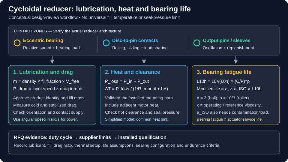
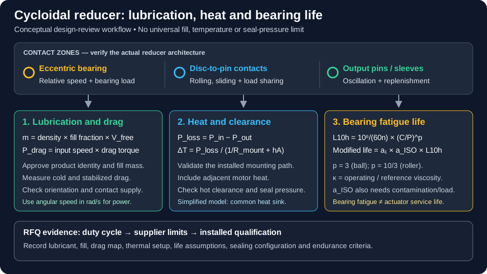
Conceptual engineering diagram, not a dimensioned assembly drawing or measured thermal map. Values in the worked examples below are assumptions for calculation only.
1. Tribological Kinematics of Cycloidal Reducers: Rolling vs. Sliding Regimes
Separate the contact zones before selecting a lubricant. Different cycloidal architectures use different bearing arrangements, disc counts, and output mechanisms; the following describes a common eccentric-disc arrangement rather than every product sold as a cycloidal reducer.
A. High-Speed Input Eccentric Bearings
The eccentric bearing carries torque reaction and dynamic loading while supporting disc motion. Its relative race speed must be derived from the mechanism; it should not automatically be equated with the motor speed. Bearing type, load distribution, fits, and temperature affect both friction and fatigue. Request the bearing identification and calculation assumptions instead of inferring dynamic capacity from the reducer's output torque rating.
B. Cycloidal Disc Lobes vs. Housing Pin Rollers
Disc-to-pin contacts combine rolling and sliding in proportions that vary with geometry and position in the mesh. Contact stress and lubricant-film requirements depend on load sharing, surface finish, material, and profile modification. Do not prescribe an extreme-pressure additive merely because the application has high torque: the complete formulation also needs compatibility with the bearing, seals, and any coatings.
C. Output Drive Pins and Disc Transmission Bores
Output pins and sleeves can experience loaded oscillation and small-amplitude motion. An actuator that mostly holds position or dithers may have different replenishment and fretting risks from one making full rotations. Include dwell, reversing, and emergency-stop events in the requirement. A continuous-speed endurance result alone does not demonstrate performance in an oscillating joint.
The NTN bearing-selection guide provides a useful framework for considering loads, speed, temperature, lubrication, sealing, and clearance together. It is bearing guidance, not a cycloidal reducer approval.
2. The Viscous Churning Mechanism & Free Cavity Fill Ratio
Packing a cavity with grease does not automatically improve protection. Fresh grease can create substantial drag until it redistributes; continued shearing can contribute heat during operation. Conversely, a stable low-drag channel is useful only if lubricant still reaches the loaded contacts. Apparent viscosity and flow depend on the complete grease formulation and its shear and temperature history.
Channeling vs. Churning Flow Regimes
During run-in, moving components displace grease from swept regions into available reservoirs. Channeling can reduce drag, while base oil release and grease movement replenish contacts. Distribution changes with orientation, speed, starts, and dwell. A drop in no-load torque may indicate redistribution or warming; it does not by itself prove adequate lubrication or completed run-in.
Compare candidate fills at the same initial temperature, speed, orientation, and stabilization condition. Record breakaway torque separately from running torque. Include repeated cold starts and inspection for grease migration so that a lower drag result cannot hide starvation.
Measuring Drag Power Instead of Assuming a Churning Law
Use a torque measurement to make the energy consequence explicit:
omega = 2 * pi * n / 60
P_drag = omega * T_drag
With speed n in RPM and measured input drag T_drag in N·m, power is in watts. For a hypothetical measurement of 0.12 N·m at 2,500 RPM, drag power is approximately 31.4 W. That total includes bearing, seal, lubricant, and other unloaded losses; it is not an isolated measurement of grease churning.
A power law fitted to another gearbox is not transferable without validation. Establish a local drag map over the approved speed, temperature, and fill range. Subtracting two tests can help compare configurations, but temperature drift, bearing preload, and seal variation must be controlled before attributing the difference to grease.
Sizing the Free Internal Volume (V_free)
Document which connected cavities are included and subtract displaced component volumes from the lubricant-accessible housing volume. A CAD void is not necessarily a usable grease reservoir throughout motion. Verify the estimate against assembly features, inaccessible spaces, and orientation.
phi_fill = V_grease / V_free
m_grease = rho_grease * phi_fill * V_free
Illustrative dispensing calculation: For a validated free volume of 60 cm³, an assumed 30% trial fill, and grease density of 0.90 g/cm³, the target mass is 16.2 g. The 30% value is an example, not a recommended universal fill. A ±1 g dispensing tolerance would be about ±6.2% of that mass and could be inappropriate for a smaller reducer. Agree the fill and tolerance from performance trials and dispenser capability.
3. Lubricant Chemistry & Formulation Selection for Sealed Robotic Joints
Specify a lubricant by approved product identity and revision, not by a generic label such as “robotics grease.” Base oil, thickener, additives, and consistency are separate properties. Polyalphaolefin (PAO) is a base oil family; polyurea is a thickener. Describing a material as “PAO/polyurea” does not establish its viscosity, compatibility, or service life.
A. Base Oil Chemistry
PAO, ester-containing, mineral-oil, and fluorinated formulations serve different requirements. Assess the actual product's viscosity–temperature curve, oxidation resistance, low-temperature torque, and compatibility with elastomers and coatings. A fluorinated formulation does not automatically qualify an assembly for vacuum, cleanroom, surgical, or food-contact service. Those environments require their own material and contamination evidence.
B. Base Oil Viscosity and Consistency
Base-oil kinematic viscosity at 40°C is a useful identification property. Obtain viscosity at the expected operating temperature for bearing calculations. Higher viscosity can improve separation in some contacts while increasing drag and cold-start demand. NLGI grade describes grease consistency, not base-oil viscosity. Neither NLGI 0/1 nor NLGI 2 is automatically correct for every compact reducer.
C. Thickener, Additives, and Compatibility
Polyurea, lithium-complex, and other thickeners can be appropriate in validated products. Generic thickener compatibility charts are only a screening aid; complete formulations and mixtures need supplier review. Do not add solid lubricants or mix greases in the field without approval. Small clearances, bearing design, and cleanliness requirements can change whether an additive is acceptable.
Lubricant Formulation Selection Matrix
These are six sourcing questions, not fictional commercial grease grades or approved temperature ratings.
| Duty or environment | Candidate direction to discuss | Required supplier evidence | Acceptance boundary |
|---|---|---|---|
| High-speed continuous joint | Lower-drag approved formulation and controlled fill | Drag map and hot viscosity data | Preserve contact lubrication at sustained temperature |
| Shock-loaded positioning axis | Suitable viscosity and anti-wear performance | Contact-load assessment and representative endurance | A four-ball result alone cannot approve the reducer |
| Sub-zero mobile robot | Product with demonstrated low-temperature behavior | Cold-soak breakaway and running torque tests | Pour point alone does not prove actuator startability |
| Vertical or changing orientation | Grease retention and replenishment strategy | Orientation-specific cycling and teardown | No universal consistency grade prevents starvation |
| Vacuum or cleanliness-controlled axis | Application-compatible low-contamination formulation | Outgassing, material, and cleanliness documentation | Ordinary industrial grease qualification is insufficient |
| Field-serviceable industrial module | Traceable refill product and procedure | Compatibility, quantity, interval, and purge instructions | Sealed-for-life hardware may prohibit field refilling |
For oil-separation quality control, specify the method and conditions. ASTM D6184 uses a conical sieve; its standard condition is 100°C for 30 hours unless the grease specification requires otherwise. The method does not predict dynamic oil separation in a running reducer, and precision data are limited for very soft greases. Do not turn an arbitrary bleed percentage into a universal actuator acceptance limit.
4. Steady-State Thermal Equilibrium & Clearance Collapse Dynamics
A reducer's thermal behavior depends on the installed assembly. A bench result on a metal fixture may not transfer to an insulated robot link or enclosed joint. Motor and drive heat can also enter the housing. Record the mounting interface, fastener condition, adjacent heat sources, airflow, and ambient temperature alongside speed and torque.
Formulating Total Power Loss (P_loss)
For steady motoring with no net change in stored energy, shaft measurements give:
P_in = T_in * omega_in
P_out = T_out * omega_out
P_loss = P_in - P_out
eta = P_out / P_in
P_loss = P_out * (1 / eta - 1)
The efficiency expression describes the complete loss represented by that efficiency measurement. Do not add measured no-load drag again if the efficiency already includes it. If using a component model instead, sum bearing, mesh, grease, and seal losses with consistent boundaries; each friction torque must use its own relative angular speed.
Acceleration, deceleration, regeneration, and motor electrical losses require a broader energy balance. A servo current reading is not automatically a calibrated reducer input-torque measurement.
Housing Temperature Rise (ΔT)
A simplified, single-temperature steady-state model is:
Delta_T = P_loss / (1 / R_mount + h * A_case)Here R_mount is an effective mounting-path resistance in K/W, h is a convection coefficient in W/(m²·K), and A_case is exposed area in m². The model assumes both paths reject heat to the same temperature reference and omits radiation and internal gradients. Real interfaces need measurement or a calibrated thermal model.
Reproducible sensitivity example: Assume 30 W of reducer heat, 0.03 m² exposed area, and h = 8 W/(m²·K). A mounting resistance of 1.2 K/W predicts a 28.0 K rise; changing only that resistance to 6 K/W predicts 73.8 K. These are hypothetical thermal paths, not material-specific constants. The result shows why mounting conductance belongs in the RFQ and why an insulated installation may need a different duty limit.
The Clearance Collapse Hazard
For a simplified equal-diameter comparison referenced to the assembly temperature:
Delta_d_relative = d * (alpha_disc * Delta_T_disc
                       - alpha_ring * Delta_T_ring)
Positive relative disc growth tends to reduce diametral clearance in this simplified model; the corresponding radial change is half as large. For equal steel expansion coefficients of 11.7 × 10^-6 /K, an 80 mm diameter and 25 K disc-to-ring temperature difference give 23.4 µm diametral, or 11.7 µm radial, relative growth. This is not a calculation of angular backlash. Housing construction, pin locations, elastic deformation, and tolerances must be included before approving a profile or preload change.
If the thermal path or clearance stack remains unknown, request a prototype validation review before assigning continuous-duty limits.
5. Calculating L10h Bearing Life via ISO 281
Basic rating life corresponds to 90% survival against rolling-contact fatigue for a population under stated conditions. For constant speed and load:
L_10h = [10^6 / (60 * n)] * (C / P)^p
p = 3 for ball bearings; p = 10/3 for roller bearings
L_nmh = a_1 * a_ISO * L_10h
C is dynamic load rating, P is equivalent bearing load in the same force units, and n is relative bearing speed in RPM. Modified life adds reliability factor a_1 and modification factor a_ISO. The latter depends on lubrication, contamination, fatigue load limit, and applied load; it cannot be assigned from κ alone. See NTN load rating and life, sections 3.2–3.4.
Reference Kinematic Viscosity (ν_1)
Use the selected bearing manufacturer's calculation method. The referenced NTN guide gives this approximation, with mean bearing diameter d_m in mm, speed in RPM, and viscosity in mm²/s (cSt):
nu_1 = 45000 * n^(-0.83) * d_m^(-0.5)   for n below 1000 RPM
nu_1 = 4500 * n^(-0.5) * d_m^(-0.5)     for n at or above 1000 RPM
kappa = nu_operating / nu_1
Arithmetic example, not a product prediction: At d_m = 42 mm and n = 2,500 RPM, the second expression gives ν_1 ≈ 13.9 cSt. Assume two hypothetical operating viscosities of 28 cSt and 14 cSt; the corresponding κ values are approximately 2.02 and 1.01. These inputs do not describe a named grease or establish temperatures at which it reaches either viscosity.
Separately, at C/P = 4.2 and the same constant relative speed, the roller-bearing basic life equation gives L10h ≈ 797 hours. It does not give 20,000 hours. Holding speed constant, a hypothetical 20,000-hour basic-life target would require C/P ≈ 11.04 before other checks. This is a sizing sensitivity, not permission to increase bearing capacity without checking envelope, minimum load, fits, or mechanism forces.
Multi-Step Robotic Duty Cycle Equivalent Load (P_eq)
For segments with the same bearing life exponent, a simplified revolution-weighted load is:
P_eq = [ sum(abs(n_k) * t_k * P_k^p)
         / sum(abs(n_k) * t_k) ]^(1/p)
n_mean = sum(abs(n_k) * t_k) / sum(t_k)
Use actual bearing loads, not output torque substituted into a force equation. Include both directions through speed magnitude. This averaging assumes compatible operating conditions and positive accumulated revolutions. Where lubrication, temperature, or contamination varies materially, use segment-specific life and a documented damage calculation. Stationary dwell, shock indentation, and small-angle oscillation require separate assessment; dividing by zero speed or relying on an RMS motor-torque value cannot address them.
Purchasing boundary: Ask whether the life statement concerns one bearing, the bearing set, or the complete reducer. A lubrication-life estimate and a bearing fatigue calculation are different deliverables. Neither alone establishes actuator warranty life.
6. Sealing Architecture, Pressure Breathing, and Ingress Protection (IP65/67)
Thermal cycling can create pressure differences in a sealed cavity. A useful first check is the ideal-gas relation for a fixed mass of trapped air:
P2_absolute = P1_absolute * (T2_kelvin / T1_kelvin) * (V1 / V2)Illustrative fixed-volume case: Heating from 25°C to 80°C, starting at 101.325 kPa absolute and with unchanged ambient pressure, produces approximately 18.7 kPa gauge (0.0187 MPa). This excludes lubricant expansion, cavity compliance, leakage, and vent flow. Reduced gas volume can increase pressure further; the result is not a seal rating or a prescribed pressure-test condition.
Seal Material Selection: FKM vs. NBR
Compare the actual NBR, FKM, or PTFE seal product against lubricant chemistry, temperature, shaft surface, speed, pressure, and cold-start behavior. Generic material names do not specify allowable combinations. Request the seal manufacturer's limits and the shaft requirements rather than assuming one elastomer is mandatory or assigning a universal failure pressure.
Pressure Relief Strategies
A membrane vent can reduce pressure differences when its flow capacity, location, and resistance to contamination suit the application. It does not guarantee zero differential pressure, exclude water vapor, or automatically preserve an assembly's IP rating. A diaphragm or other compensator is another option when external breathing is unsuitable, but it needs sufficient travel and compatible materials.
Agree headspace and thermal-expansion allowances with the reducer supplier. Test sealing and ingress protection on the complete configuration, including connectors, joints, vent, mounting orientation, and the relevant exposure. Do not apply an arbitrary pressure-decay test to hardware whose seals or vent were not designed for it.
7. Tribological Failure Modes & Field Diagnostic Matrix
Use symptoms to generate testable hypotheses. A teardown signature rarely proves a single root cause without operating history, lubricant identification, and dimensional evidence.
| Failure mode observed | Possible mechanism | Evidence to collect | Corrective decision to validate |
|---|---|---|---|
| Pin or disc surface micropitting | Inadequate film, roughness, or contact loading | Surface inspection, lubricant condition, load history | Reassess contact geometry, viscosity, cleanliness, and duty |
| Eccentric bearing spalling | Rolling fatigue or secondary damage | Bearing identity, raceway pattern, force spectrum | Recalculate bearing load and life; inspect fits and contamination |
| Grease hardening or separation | Ageing, incompatible mixture, or poor redistribution | Product identity, sample condition, temperature log | Review formulation, storage, fill, and thermal exposure |
| Shaft seal wear or oil weeping | Pressure, shaft damage, incompatibility, or assembly error | Shaft finish, lip inspection, cavity pressure trace | Validate seal, shaft, assembly, and compensation together |
| Rising hot running torque | Clearance change, preload, drag, or damage | Cold/hot torque, temperatures, dimensional stack | Review thermal path and clearance before changing profiles |
| Fretting at output pins | Loaded micro-motion with insufficient replenishment | Motion spectrum, surface marks, debris analysis | Qualify lubricant and contact design under actual oscillation |
Do not automatically prescribe thicker grease, a different thickener, a coating, or radial relief from this matrix. Each can change drag, contact stress, leakage, or accuracy elsewhere in the actuator. Confirm the hypothesis on representative hardware before issuing a production change.
8. Engineering & Procurement RFQ Inspection Gates (Checklist)
Use these eight gates to make supplier submissions comparable. They separate production controls from type and endurance qualification; not every test belongs on every shipped unit.
- Gate 1 — Lubricant identity and traceability: Record the approved trade name, revision, base oil, thickener, viscosity data, batch identification, and applicable certificates. Agree substitution control and mixing restrictions.
- Gate 2 — Fill quantity and dispensing control: Document the definition of free volume, approved grease mass, tolerance, assembly orientation, and dispenser calibration. Require quantity records at the agreed sampling level.
- Gate 3 — Run-in procedure: Obtain approved speed, duration, load, temperature stop limits, and cooling conditions. Distinguish a production settling process from a design qualification; do not impose a generic high-speed sequence.
- Gate 4 — Drag acceptance map: Define cold breakaway and stabilized running torque at agreed speeds and temperatures. Record fixture drag and measurement uncertainty. Establish limits from validated samples and the motor's available torque margin.
- Gate 5 — Installed thermal qualification: Test the customer's duty, mounting conductance, ambient range, and nearby heat sources. Agree sensor locations and a temperature-slope criterion for stabilization instead of assuming a fixed four-hour run proves equilibrium.
- Gate 6 — Seal and ingress evidence: Identify the exact seal and vent configuration, allowable pressure range, leak method, and required ingress test. Use supplier-approved proof conditions and document any restrictions after thermal cycling.
- Gate 7 — Bearing fatigue calculation: Request bearing identities, relative speeds, force spectrum, reliability level, operating viscosity, contamination assumptions, and life factors. State which parts and failure modes are covered and the agreed hour target.
- Gate 8 — Endurance and post-test inspection: Agree cycles, environmental exposure, sample count, teardown criteria, and lubricant-analysis baselines. A shorter accelerated test needs a justified acceleration model before it supports a longer service-life claim.
For bid comparison, mark missing evidence as open rather than assigning a pass based on the brand of grease or a “lubricated for life” statement. Ask who owns each deliverable, when the evidence is due, and whether a quoted cost includes qualification. This prevents a technically incomplete low-price proposal from appearing equivalent to a documented design.
9. Frequently Asked Questions (FAQ)
Can we use standard EP2 lithium grease to top off a cycloidal reducer in the field?
Only follow the approved service instructions. “EP2” is insufficient to identify a compatible replacement. Mixing may alter consistency or separation behavior, but immediate failure is not inevitable for every lithium/polyurea combination. Confirm complete-product compatibility and refill quantity with the supplier. Some sealed assemblies prohibit field replenishment entirely.
How does cold ambient temperature (-20°C to 0°C) affect starting torque?
Cold grease can increase breakaway and running torque. The increase depends on the formulation, fill, seals, speed, and cold-soak duration; a universal three-to-five-times multiplier is unreliable. Request actuator-level cold-start measurements and check motor and drive torque availability at the minimum supply voltage. Pour point alone is not a starting-torque specification.
Why does vertical mounting risk grease starvation?
Gravity and motion can move lubricant away from some contacts, depending on the internal reservoirs and grease behavior. Test the intended vertical orientation, reversals, dwell, and long stationary periods. A grease baffle or different consistency may help a particular design, but neither can be selected from orientation alone.
What is the maximum acceptable continuous housing temperature?
There is no universal housing-temperature limit for sealed cycloidal reducers. Establish the limit from the approved lubricant, seals, bearings, clearances, and adjacent motor or sensor ratings. Housing temperature is a measurement location, not a fixed offset from every internal contact. Validate that relationship on the installed assembly and define shutdown behavior separately.
How does thermal behavior compare with a strain wave drive?
Compare complete assemblies at the same ratio, output duty, temperature, and mounting conditions. Both can have load-dependent, lubricant, bearing, and seal losses. A generic efficiency percentage or mechanism label cannot predict which actuator runs cooler. Request comparable efficiency maps, unloaded drag, and thermal tests at the operating points that matter.
Can vacuum filling or degassing improve consistency?
It may help a validated dispensing process control entrained air and quantity. It does not establish better bearing life or heat transfer by itself. Ask for evidence comparing the proposed process with the baseline, including grease condition, mass repeatability, and lubricant distribution. Do not prescribe ultrasonic treatment without lubricant-manufacturer approval.
Why do some manufacturers recommend oil instead of grease?
Oil systems may suit cooling, circulation, and replenishment requirements; grease can simplify retention and assembly. The choice depends on the architecture, speed, sealing, maintenance, and orientation. Neither lubricant type is mandatory for all robotic or industrial reducers. Follow the selected product's lubrication specification rather than converting it using a generic viscosity grade.
Does oil weeping prove internal pressure buildup?
No. Pressure is one possible cause alongside seal damage, shaft finish, assembly error, incompatible materials, and lubricant separation. Measure pressure and correlate leakage with thermal cycling before changing vents or seals. Rising idle current is also nonspecific and needs torque, temperature, and mechanical inspection to support a diagnosis.
10. Standards, References & Literature
Sources checked for this review on 12 November 2026. Manufacturer guidance supports bearing selection and calculation; it does not certify the example actuator. Full standards and product-specific approval remain necessary for contractual acceptance.
- NTN — Ball and Roller Bearings, chapter 2: Bearing selection, printed pages A-14–A-19. Selection workflow covering operating conditions, loads, lubrication, seals, and clearance.
- NTN — Ball and Roller Bearings, chapter 3: Load rating and life, sections 3.2–3.4, printed pages A-20–A-27. Basic and modified rating life, viscosity ratio, and ISO 281:2007 calculation context. The worked arithmetic here is illustrative, not an NTN product rating.
- ASTM D6184 — Oil Separation from Lubricating Grease, Conical Sieve Method. Official method scope, test conditions, and limitations; use the contractually specified edition. This quality-control method is not a dynamic reducer endurance test.
11. Engineering Consultation & RFQ Support
For sealed actuator sourcing, bring the speed–torque–time spectrum, target operating hours and reliability, ambient range, mounting drawing, orientation, cold-start constraints, and any ingress or cleanliness requirements. State prototype quantity and planned annual volume so the proposal can distinguish design qualification from routine production inspection.
- Compare integration envelopes through Compact Cycloidal Gearboxes and Compact Humanoid Cycloidal Reducers.
- For a custom motor-and-reducer housing, review Cycloidal Drive Components and identify who owns grease containment, bearing supports, and the thermal interface.
- Use OEM Prototype Validation Services to discuss a qualification plan, or submit the operating envelope for an engineering RFQ.
Request a response that identifies the approved lubricant and fill, predicted thermal limits, covered life calculation, required tests, and unresolved assumptions. Special lubricant, vacuum, medical, or food-grade requirements need explicit confirmation of capability and evidence before they become purchase-order commitments.
Author

Categories
More Posts
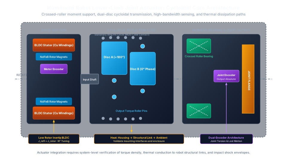
Humanoid Robot Knee and Ankle Actuators: Cycloidal Reducer Selection for Foot-Strike Shock Loads, Reflected Inertia (J·N²), Backdrivability, and Sealed Limb Thermal Runaway
Select cycloidal reducers for humanoid knee and ankle joints: compare shock loads, reflected inertia and sealed-limb heat. Use the RFQ checklist to plan tests.
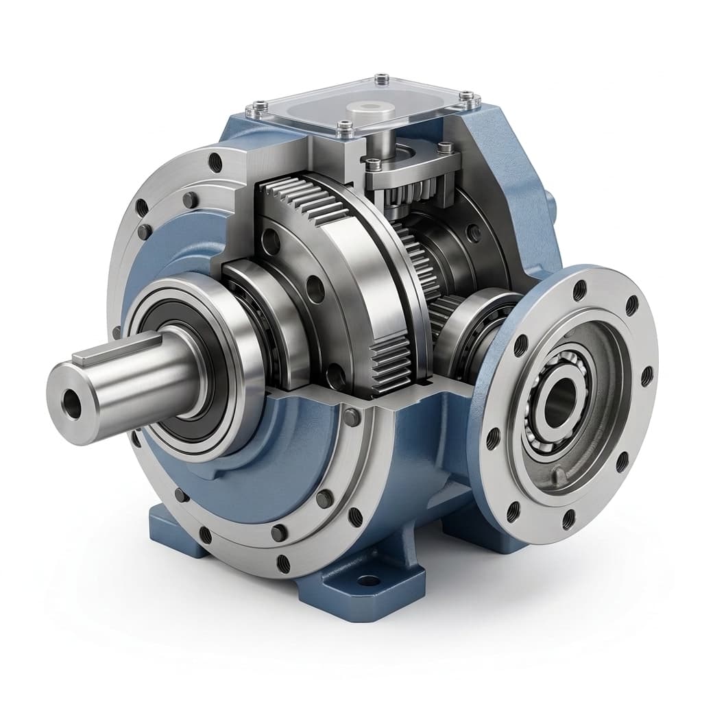
How to Select the Right Cycloidal Reducer for AGV and AMR Drive Wheels
A highly technical sizing guide for OEM engineers selecting cycloidal reducers for Automated Guided Vehicles (AGVs). Includes torque formulas, radial load calculations, and duty cycle analysis.
Hollow Shaft Cycloidal Reducers for Robot Joints: Through-Bore Sizing, Cable Routing, and Tilting Moment Bearing Capacity
Size hollow shaft cycloidal reducers for robot joints: check cable clearance, bend limits, and tilting moment capacity. Prepare your RFQ for engineering review.